Light control signal generating circuit

a technology of light control and signal generation circuit, which is applied in the field of circuits, can solve the problems of complex circuit structure and high cost of special integrated chips

Active Publication Date: 2012-07-12
FU TAI HUA IND SHENZHEN +1
View PDF8 Cites 3 Cited by
  • Summary
  • Abstract
  • Description
  • Claims
  • Application Information

AI Technical Summary

Problems solved by technology

However, the special integrated chip is very expensive and the circuit structure is complex.

Method used


Image

  • Light control signal generating circuit
  • Light control signal generating circuit
  • Light control signal generating circuit

Examples


Embodiment Construction

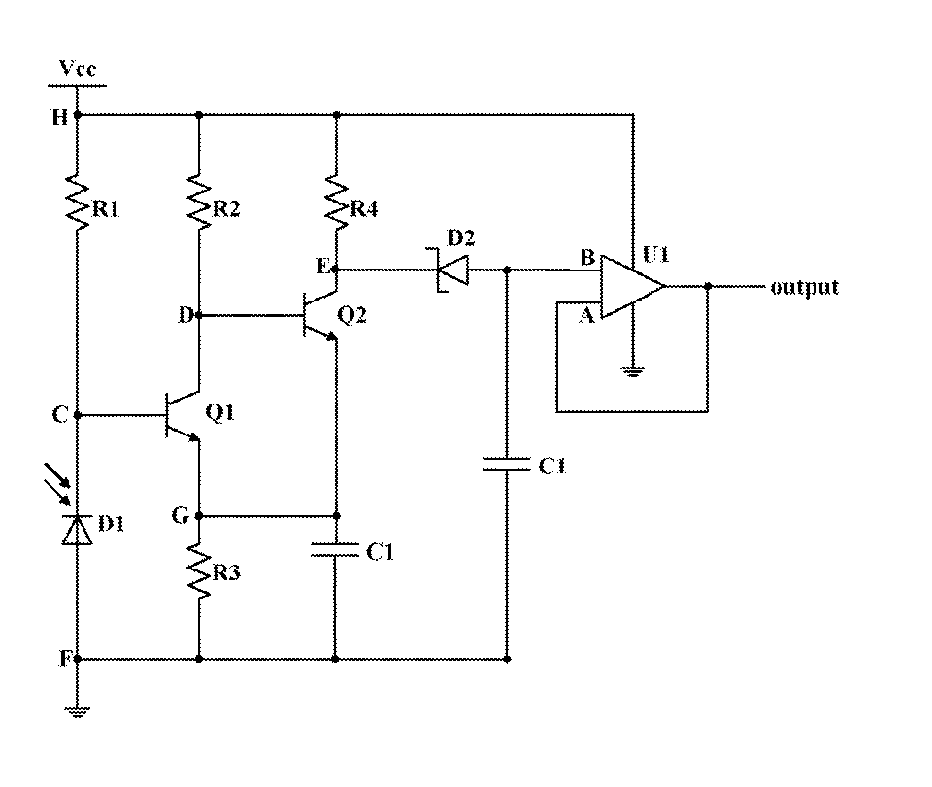
[0008]FIG. 1 is a block diagram of a light control signal generating circuit in accordance with an exemplary embodiment. The light control signal generating circuit (hereinafter “the circuit”) 1 is utilized for outputting a stable level voltage according to received ambient light, such as a stable high or low level voltage. The circuit 1 includes a photosensitive element 10, a signal converting circuit 20, and a voltage stabilizing circuit 30. The photosensitive element 10 is configured for receiving ambient light. When a signal strength of the ambient light is greater than or equal to a preset value, the photosensitive element 10 is turned on. When the signal strength of the ambient light is less than the preset value, the photosensitive element 10 is turned off.

[0009]When the photosensitive element 10 is turned on, the signal converting circuit 20 outputs a low level voltage. When the photosensitive element 10 is turned off, the signal converting circuit 20 outputs a high level vo...


PUM


Abstract

A light control signal generating circuit includes a photosensitive element, two transistors, and four resistances. A first resistance and the photosensitive element are connected in series between a power voltage terminal and a ground terminal. A base electrode of a first transistor is connected to a node between the first resistance and the photosensitive element, a collecting electrode is connected to the power voltage terminal through a second resistance, and an emitting electrode is connected to the ground terminal through a third resistance. A base electrode of a second transistor is connected to a node between the second resistance and the first transistor, a collecting electrode is connected to the power voltage terminal through a fourth resistance, and an emitting electrode is connected to the ground terminal through the third resistance. An output terminal is formed from a node between the fourth resistance and the second transistor.

Description

BACKGROUND[0001]1. Technical Field[0002]The disclosure relates to a circuit and, more particularly, to a light control signal generating circuit.[0003]2. Description of Related Art[0004]A light control circuit often includes a special integrated chip, such as a 555 chip. However, the special integrated chip is very expensive and the circuit structure is complex.[0005]Therefore, what is needed is a light control signal generating circuit to overcome the described shortcoming.BRIEF DESCRIPTION OF THE DRAWINGS[0006]FIG. 1 is a block diagram of a light control signal generating circuit in accordance with an exemplary embodiment.[0007]FIG. 2 is a circuit diagram of the circuit of FIG. 1.DETAILED DESCRIPTION[0008]FIG. 1 is a block diagram of a light control signal generating circuit in accordance with an exemplary embodiment. The light control signal generating circuit (hereinafter “the circuit”) 1 is utilized for outputting a stable level voltage according to received ambient light, such...

Claims


Application Information

Patent Timeline
IPC IPC(8): H05B37/02
CPCG01J1/44G01J1/32Y02B20/48Y02B20/46H05B37/0218H05B47/11Y02B20/40
InventorYIN, JI-XIANGHUANG, REN-WENZHANG, JUN-WEIZHANG, JUNCHUANG, TSUNG-JEN
OwnerFU TAI HUA IND SHENZHEN