Frequency domain compression in a base transceiver system

a transceiver system and frequency domain technology, applied in the field of compression and decompression of communication signals in a transceiver system, can solve the problems of large number or capacity, cpri or obsai standards that cannot be met by radio base transceiver systems, and require expensive hardware upgrades to transceiver systems. , to achieve the effect of improving overall communication throughput, reducing processing overhead, and significant compression

Active Publication Date: 2012-07-12
INTEGRATED DEVICE TECH INC
View PDF7 Cites 154 Cited by
  • Summary
  • Abstract
  • Description
  • Claims
  • Application Information

AI Technical Summary

Benefits of technology

[0018]As a result of the techniques described herein, significant compression is achieved with relatively low processing overhead, along with significant improvements in overall communications throughput for the base station transceiver system.

Problems solved by technology

Proprietary or other modular designs for radio base transceiver systems may not comply with CPRI or OBSAI standards.
The need to comply with evolving wireless communication standards, increase data volume and serve more subscribers, may require expensive hardware upgrades to transceiver systems, including increasing the number or capacity of serial data links and increasing the data processing capability of supporting subsystems.
These requirements can conflict with constraints on transceiver systems, including physical size limitations, power consumption limitations and geographic restrictions.

Method used


Image

  • Frequency domain compression in a base transceiver system
  • Frequency domain compression in a base transceiver system
  • Frequency domain compression in a base transceiver system

Examples


Embodiment Construction

[0042]The following describes frequency domain compression and decompression of signal samples for transfer in base transceiver systems. Example architectures of base transceiver systems include a general base station, OBSAI or CPRI base stations and distributed antenna systems. The preferred methods for compression and decompression applied to the signal samples processed by the transceiver systems are then described.

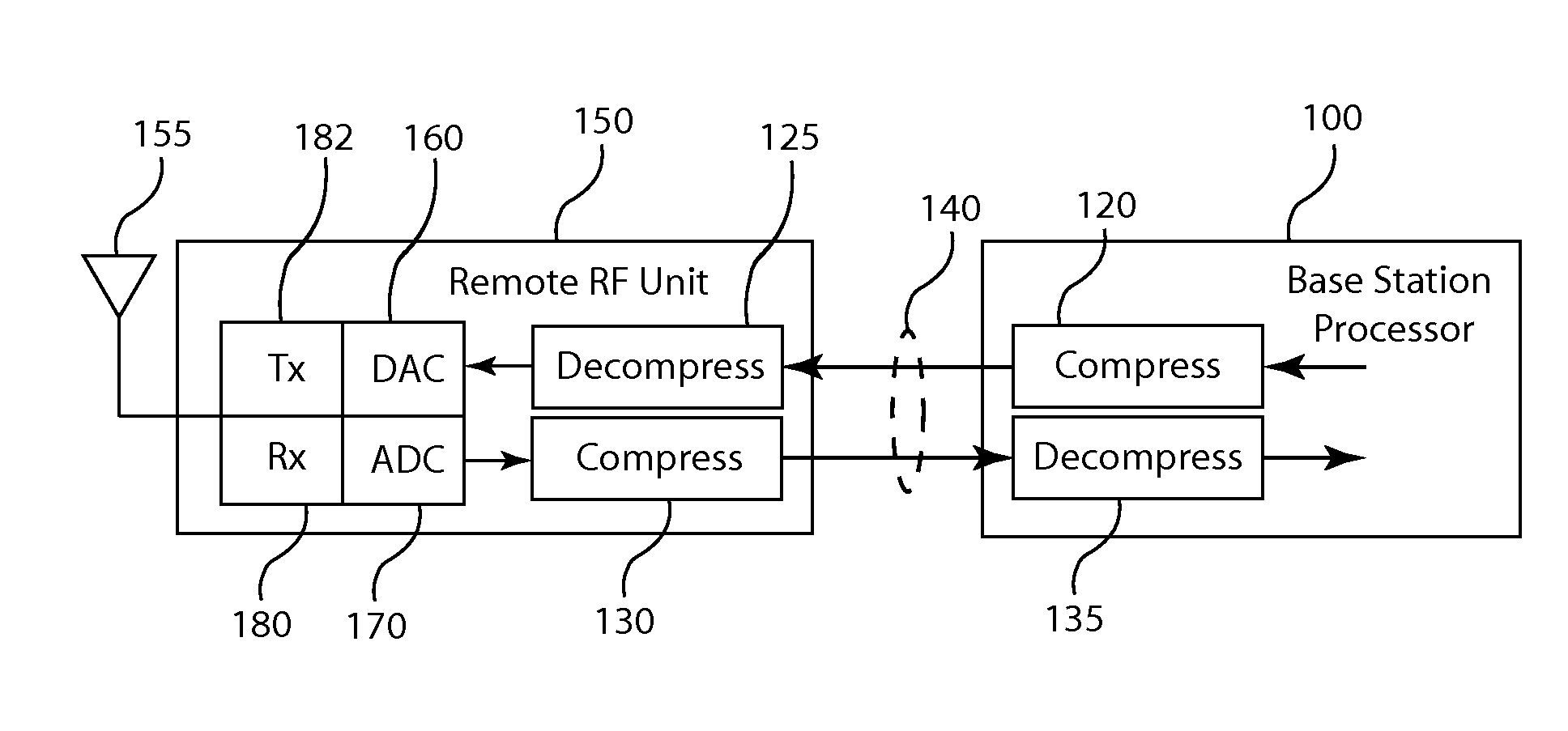
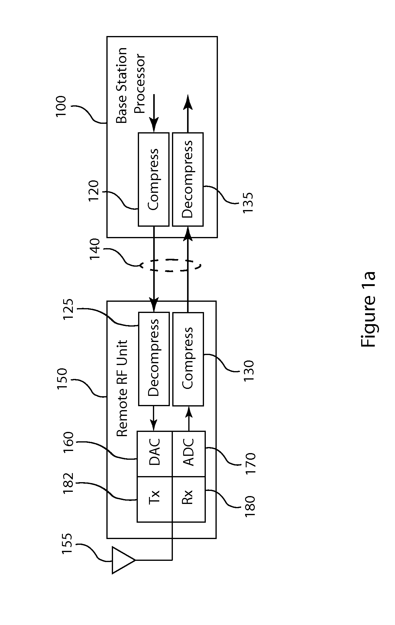
[0043]FIG. 1a is a block diagram of a general base station architecture that incorporates frequency domain compression and decompression in accordance with the technology described herein. The BTS architecture includes the base station processor 100 connected by one or more serial data links 140 to an RF unit 150. This general architecture can be used for any air interface standard employed by a wireless communication network, including GSM / EDGE, code division multiple access (CDMA) based modulation formats, orthogonal frequency division multiplexing (OFDM) based modul...


PUM


Abstract

A method and apparatus provide signal compression for transfer over serial data links in a base transceiver system (BTS) of a wireless communication network. For the uplink, an RF unit of the BTS applies frequency domain compression of baseband signal samples, resulting from analog to digital conversion of received analog signals followed by digital downconversion, forming compressed coefficients. After transfer over the serial data link, the baseband processor then applies frequency domain decompression to the compressed coefficients prior to normal signal processing. For the downlink, the baseband processor applies frequency domain compression of baseband signal samples and transfers the compressed coefficients to the RF unit. The RF unit applies frequency domain decompression to the compressed coefficients prior to digital upconversion and digital to analog conversion, generating the analog signal for transmission over the antenna. This abstract does not limit the scope of the invention as described in the claims.

Description

CROSS-REFERENCE TO RELATED APPLICATIONS[0001]This application claims priority to U.S. Provisional Patent Application No. 61 / 430,901, filed on Jan. 7, 2011 and entitled, “Frequency Domain Compression in a Base Transceiver System”.BACKGROUND OF THE INVENTION[0002]The technology described herein relates to compression and decompression of communication signals in a transceiver system of a wireless communication network and, particularly, to compressing signal samples in the frequency domain prior to transfer over a serial data link between devices in a base transceiver system or a distributed antenna system.[0003]Transceiver systems in wireless communication networks perform the control functions for directing signals among communicating subscribers, or terminals, as well as communication with external networks. The general operations of a radio transceiver system include receiving radio frequency (RF) signals, converting them to signal data, performing various control and signal proce...

Claims


Application Information

Patent Timeline
Patent Type & Authority Applications(United States)
IPC IPC(8): H04W4/00
CPCH04B1/40H04W88/085H04L25/03H04L27/2615H04L27/2628H04L27/2647
Inventor LING, YI
Owner INTEGRATED DEVICE TECH INC
Why Eureka
Try Eureka