Heat dissipation assembly

a technology of heat dissipation assembly and heat dissipation assembly, which is applied in the direction of lighting and heating apparatus, instruments, and semiconductor/solid-state device details, etc., can solve the problems of deteriorating operational stability, damage to associated elements, and low heat dissipation efficiency

Inactive Publication Date: 2012-07-19
HONG FU JIN PRECISION IND (SHENZHEN) CO LTD +1
View PDF5 Cites 3 Cited by
  • Summary
  • Abstract
  • Description
  • Claims
  • Application Information

AI Technical Summary

Problems solved by technology

With developments in computing technology, electronic devices such as central processing units (CPUs) generate excessive heat during normal operation, which can deteriorate operational stability and damage associated elements.
However, the heat dissipation efficiency is often low.

Method used


Image

  • Heat dissipation assembly
  • Heat dissipation assembly
  • Heat dissipation assembly

Examples


Embodiment Construction

[0010]The disclosure is illustrated by way of example and not by way of limitation in the figures of the accompanying drawings in which like references indicate similar elements. It should be noted that references to “an” or “one” embodiment in this disclosure are not necessarily to the same embodiment, and such references mean at least one.

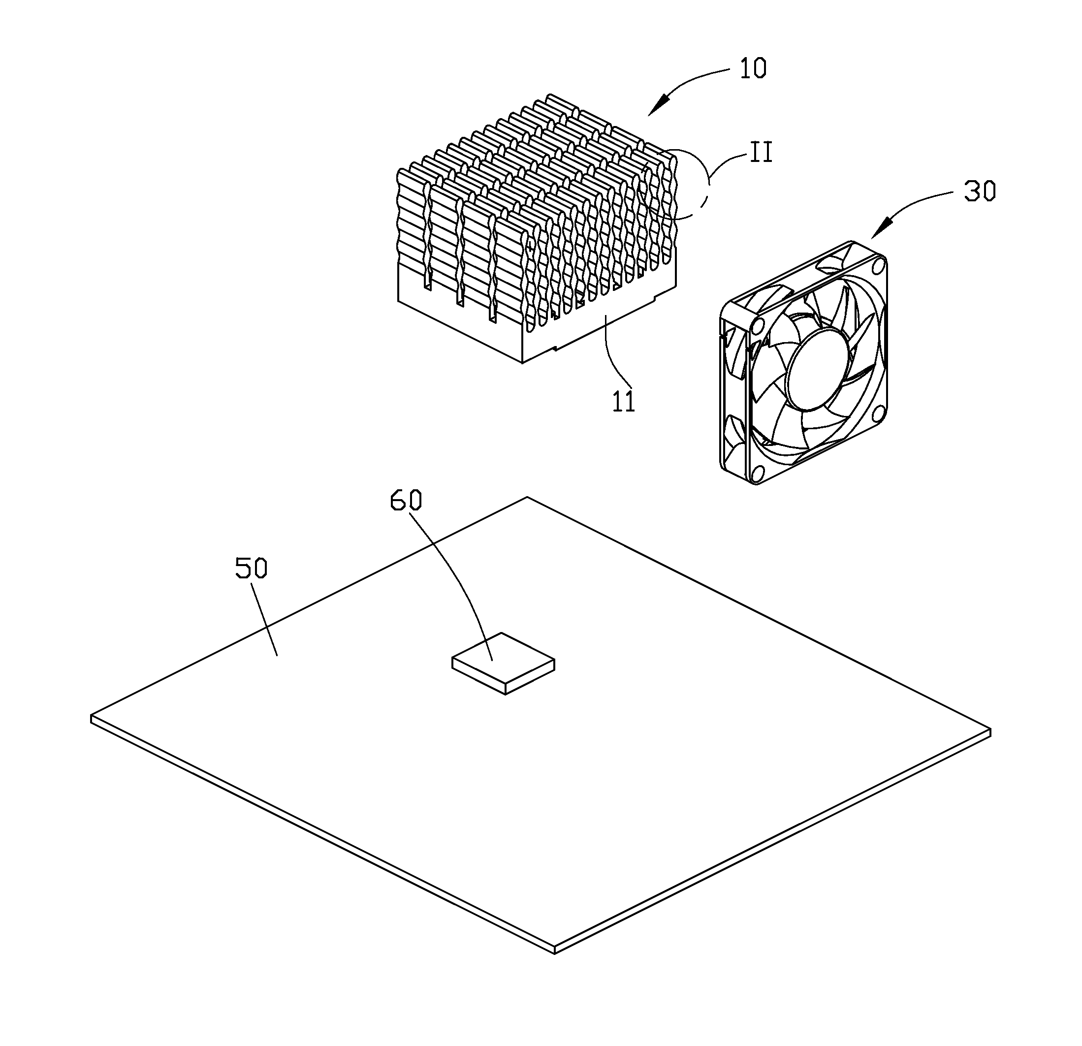
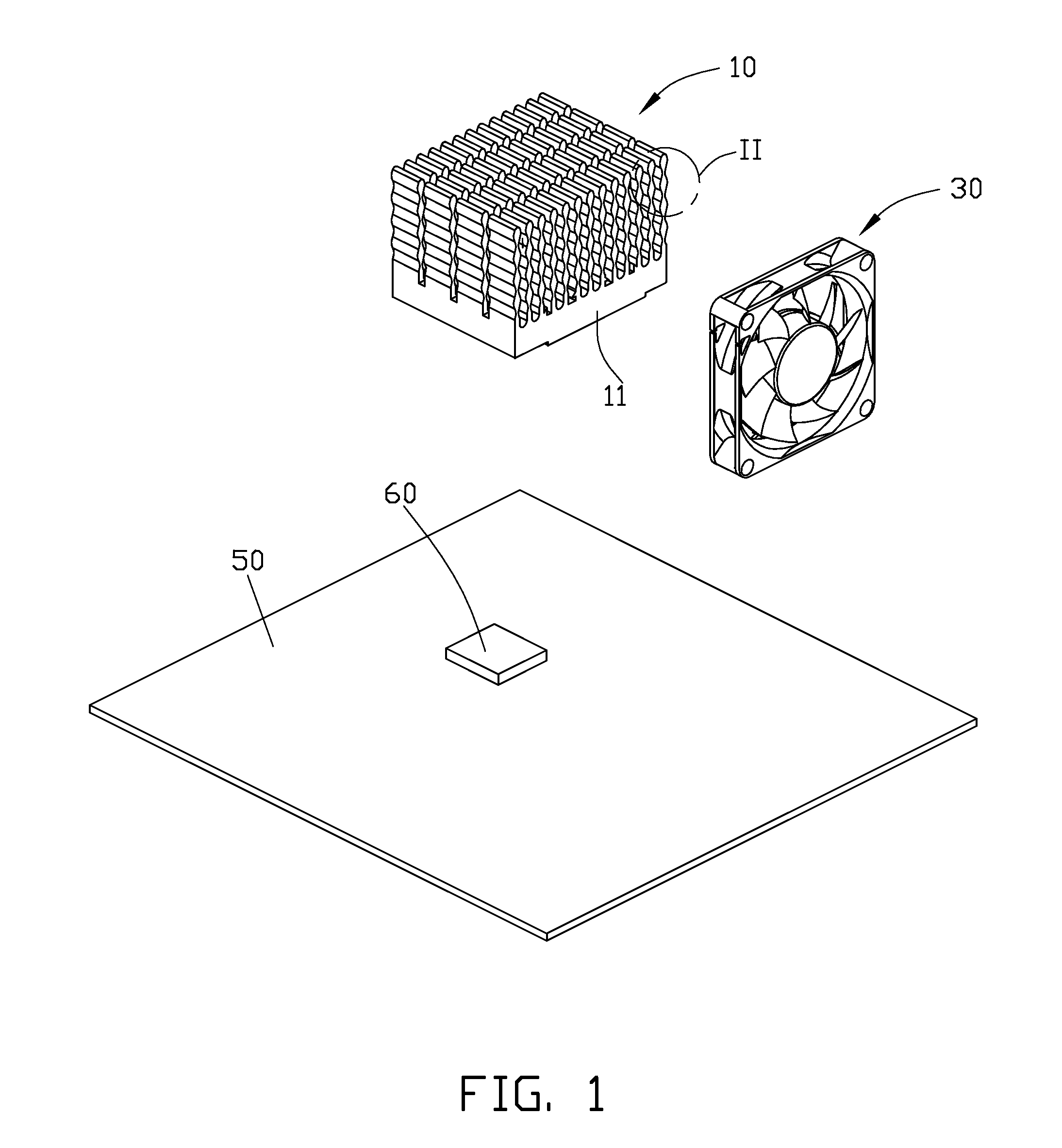
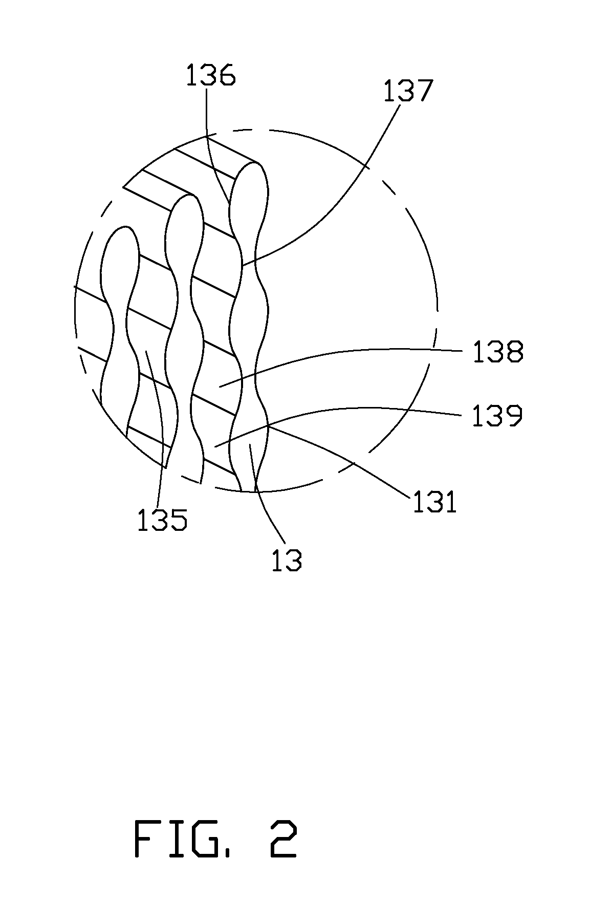
[0011]Referring to FIGS. 1 to 3, a heat dissipation assembly in accordance with an exemplary embodiment includes a heat sink 10 and a fan 30.

[0012]The heat sink 10 includes a base 11. A plurality of fins 13 is located on a top surface of the base 11. A bottom surface of the base 11 thermally contacts a heat generating component 60. In one embodiment, the heat generating component 60 is a CPU, which is located on a printed circuit board 50. Heat generated by the heat generating component 60 is transmitted to the base 11, and then transmitted to the fins 13. The fins 13 are parallel with each other. Each fin 13 includes two opposite side faces 131....


PUM


Abstract

A heat dissipation assembly includes a heat sink and a fan. The heat sink includes a plurality of fins. The plurality of fins is parallel with each other. Each of the plurality of fins includes two side faces. Each side face is waved. An air channel is located between two adjacent side faces of two adjacent fins. The air channel includes a plurality of wide portions and a plurality of narrow portions interlaced with the plurality of wide portions. The fan is located on a side of the air channel. The fan is adapted to drive air flowing fast in the plurality of narrow portions of the air channel and flowing slow in the plurality of wide portions of the air channel.

Description

BACKGROUND[0001]1. Technical Field[0002]The present disclosure relates to heat dissipation assemblies, and particularly relates to a heat dissipation assembly for removing heat from an electronic component.[0003]2. Description of Related Art[0004]With developments in computing technology, electronic devices such as central processing units (CPUs) generate excessive heat during normal operation, which can deteriorate operational stability and damage associated elements. The heat must be removed quickly. A commonly used heat dissipation component includes a heat sink mounted on a CPU. The heat sink may include a plurality of parallel fins and several heat pipes passing therethrough. A fan is mounted on the fins to dissipate heat from the fins. However, the heat dissipation efficiency is often low.[0005]Therefore, there is room for improvement within the art.BRIEF DESCRIPTION OF THE DRAWINGS[0006]Many aspects of the embodiments can be better understood with references to the following ...

Claims


Application Information

Patent Timeline
Patent Type & Authority Applications(United States)
IPC IPC(8): F28F13/00
CPCG06F1/20H01L23/3672H01L23/467H01L2924/0002H01L2924/00
Inventor ZHU, CHAO-JUNZENG, XIANG-KUNYAO, ZHI-JIANGXU, LI-FU
Owner HONG FU JIN PRECISION IND (SHENZHEN) CO LTD
Why Eureka
Try Eureka