Mount structure of touch input device having pressure sensitive sensor

a technology of touch input device and mounting structure, which is applied in the direction of instruments, force measurement, computing, etc., can solve the problem that the sensor in the patent literature 1 cannot be applied to the electronic device having the touch panel, and achieve the effect of improving pressure measurement accuracy, preventing the lowering of visibility of the display part, and avoiding the lowering of the inner side part surrounded by the fram

Inactive Publication Date: 2012-07-19
NISSHA PRINTING COMPANY
View PDF20 Cites 138 Cited by
  • Summary
  • Abstract
  • Description
  • Claims
  • Application Information

AI Technical Summary

Benefits of technology

[0047]According to the mount structure of the touch input device having the pressure sensitive sensor in the present invention, since the pair of electrodes of the pressure sensitive sensor is arranged in the shape of the frame along the edge part of the first or second substrate, transmittance of the inner side part surrounded by that frame is not lowered. Therefore, when the display part of the display device is arranged inside the frame, the visibility of the display part can be prevented from being lowered.
[0048]In addition, the pressure concentration member is arranged on the side of the back surface of the pressure sensitive sensor just under the position of the pressure sensitive ink member, so that when the pressed force is applied to the pressure sensitive sensor in the thickness direction, the part corresponding to the pressure sensitive ink member of the lower film is supported from below, and the applied pressed force is not dispersed. Therefore, the pressure measurement accuracy can be improved.
[0049]In addition, the frame-shaped gasket is arranged between the pressure sensitive sensor and the support part of the casing, so that even when the lower surface of the pressure sensitive sensor is not flat due to the presence of the pressure concentration member, the space in the frame is sealed by the frame-shaped gasket. Therefore, excellent water-proofness and dust-proofness can be provided.
[0050]Furthermore, since the gasket does not overlap with the pressure concentration member, the pressure does not concentrate on the part corresponding to the pressure sensitive ink member of the lower film when the pressed force is not applied to the pressure sensitive sensor in the thickness direction, so that the pressure concentrates for the first time when the pressed force is actually applied to the pressure sensitive sensor in the thickness direction, and the resistance changes as the detection value becomes wide. Therefore, the pressure can be easily detected.

Problems solved by technology

Therefore, the sensor in the patent literature 1 cannot be applied to the electronic device having the touch panel as it is.

Method used


Image

  • Mount structure of touch input device having pressure sensitive sensor
  • Mount structure of touch input device having pressure sensitive sensor
  • Mount structure of touch input device having pressure sensitive sensor

Examples


first embodiment

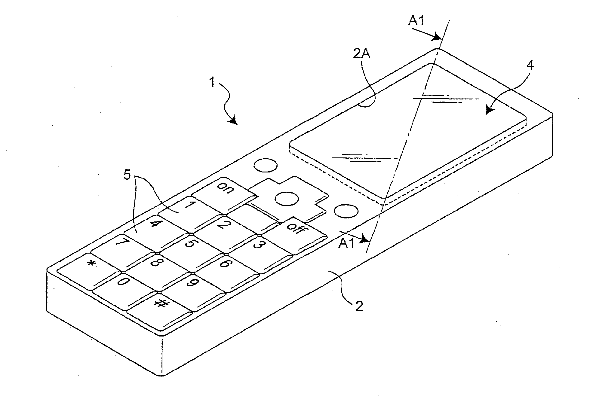
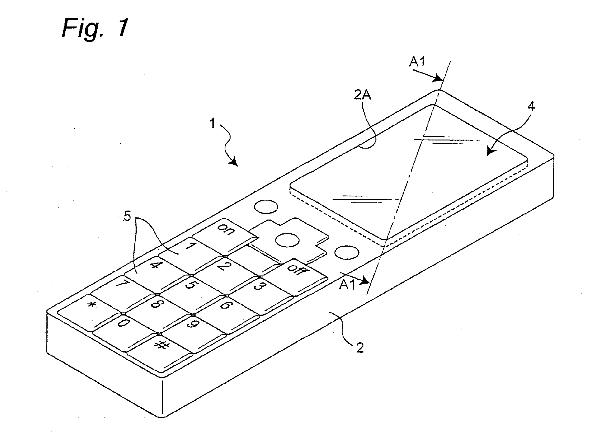
[0077]According to a mount structure of a touch input device in a first embodiment of the present invention, a touch panel and a pressure sensitive sensor integrally configure a touch input device, and the touch input device having the pressure sensitive sensor is externally mounted in a casing. The touch input device in the first embodiment can detect a strength of a pressed force by the pressure sensitive sensor, in addition to position detection in the touch panel. The touch input device in the first embodiment appropriately functions as a touch input device of a display of an electronic device having a touch panel, especially a portable electronic device such as a mobile telephone or a game machine. Here, a description will be given of an example in which this touch input device is mounted on the portable telephone.

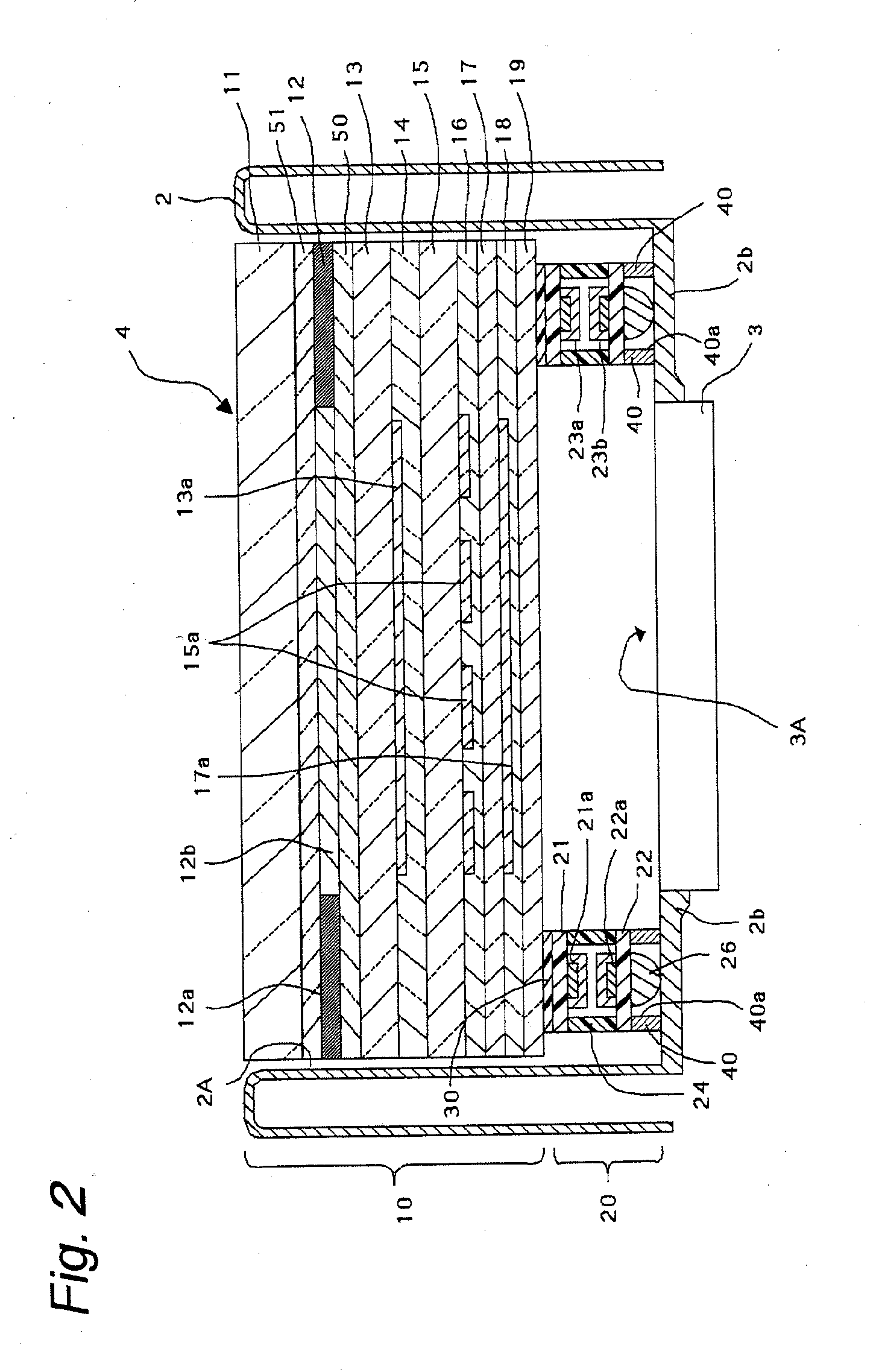
[0078]FIG. 1 is a perspective view of a portable telephone on which the touch input device according to this first embodiment is mounted, and FIG. 2 is a cross-sectio...

second embodiment

[0127]FIG. 20 is a cross-sectional view showing a mount structure of a touch input device according to a second embodiment of the present invention. The mount structure of the touch input device according to this second embodiment differs from the mount structure of the touch input device according to the first embodiment in that the gasket 40 and the pressure concentration members 26 are provided so as not to overlap with each other due to a positional relationship in which all of the pressure concentration members 26 are arranged inside the frame of the frame-shaped gasket 40, compared to the case where the gasket 40 and the pressure concentration members 26 are provided so as not to overlap with each other by providing the through holes 40a in the frame-shaped gasket 40 to house the pressure concentration member 26 in the first embodiment.

[0128]In addition, in a case where the pressure concentration members 26 are positioned outside the frame, instead of being positioned inside t...


PUM


Abstract

[Subject] To provide a mount structure of a touch input device having a pressure sensitive sensor in which visibility can be prevented from being lowered even when the pressure sensitive sensor is mounted, water-proofness and dust-proofness are excellent, and a pressure can be easily detected with high measurement accuracy.[Solution] According to a mount structure of a touch input device which includes a touch input device having at least a touch panel, and a pressure sensitive sensor attached to a lower surface thereof, and a casing dented to allow the device to be externally fitted in, and having a concave part or an opening part for a display device, and a frame-shaped support part to support a back surface peripheral part of the touch input device, in its bottom surface, the pressure sensitive sensor includes a pressure concentration member laminated and arranged in a dot shape so as to support the pressure sensitive ink member on a back surface, and a frame-shaped gasket is attached between the pressure sensitive sensor and the support part of the casing, in which the gasket does not overlap with the pressure concentration member.

Description

TECHNICAL FIELD[0001]The present invention relates to a mount structure of a touch input device having a pressure sensitive sensor to measure a pressure in a direction vertical to a surface to which an external force is applied.BACKGROUND ART[0002]Conventionally, as a pressure sensitive sensor to measure a pressure of an external force (also referred to as pressed force) applied to a certain surface, there is a sensor as disclosed in a patent literature 1 (Japanese Unexamined Patent Publication No. 2002-48658). According to the sensor in the patent literature 1, plastic films each formed by laminating an electrode and a pressure sensitive ink layer in this order sandwich an insulating layer having bonding layers on its front and back surfaces in such a manner that their pressure sensitive ink members are opposed to each other. In addition, according to the sensor in the patent literature 1, since irregularities are provided on a surface of the pressure sensitive ink layer, a certain...

Claims


Application Information

Patent Timeline
Patent Type & Authority Applications(United States)
IPC IPC(8): G06F3/041
CPCG01L1/205G06F2203/04105G06F3/0445G06F3/0446G06F3/04142G06F3/041
Inventor ENDO, YUKOTAKAI, YUICHIROKAI, YOSHIHIROSUZUKI, TAKAHIRO
Owner NISSHA PRINTING COMPANY
Why Eureka
Try Eureka