Packet restoration method, packet restoration system, and mobile terminal and intermediate device used in the method

a packet recovery and recovery method technology, applied in the field of packet recovery methods, can solve problems such as reducing the convenience of applications, and achieve the effects of improving communication efficiency, improving communication efficiency, and improving communication efficiency

Active Publication Date: 2012-07-19
PANASONIC INTELLECTUAL PROPERTY CORP OF AMERICA
View PDF5 Cites 64 Cited by
  • Summary
  • Abstract
  • Description
  • Claims
  • Application Information

AI Technical Summary

Benefits of technology

[0013]In view of the above problem, it is an object of the present invention to provide a packet recovery method, a packet recovery system, and a mobile terminal and an intermediate device (gateway device) used in the method, in which the gateway device decides on a flow as an information notification target upon a packet discard based on packet filter information registered by the mobile terminal, and the gateway device transmits a packet discard (loss) notification on the decided flow to the mobile terminal, and when the packet is actually discarded, the mobile terminal as the packet receiving node is notified thereof and enabled to transmit a retransmission request to the packet transmitting node in real time, so that the mobile terminal can improve communication efficiency without wasting retransmission latency in vain.
[0014]In order to achieve the above object, according to the present invention, there is provided a packet recovery method for recovering a packet discarded by an intermediate device positioned on a communication path between a mobile terminal and a correspondent node of the mobile terminal among packets exchanged between the mobile terminal and the correspondent node, the method including: a step of causing the intermediate device to transmit a discard notification message to the mobile terminal based on information on a communication flow for which transmission of the discard notification message indicating that the packet has been discarded is required; and a step of causing the mobile terminal to transmit the correspondent node a retransmission request message for requesting retransmission of the discarded packet based on the discard notification message. According to this configuration, communication efficiency can be improved without wasting retransmission latency in vain.
[0015]According to the present invention, there is also provided a packet recovery system for recovering a discarded packet, which includes a mobile terminal, a correspondent node of the mobile terminal, and an intermediate device positioned on a communication path between the mobile terminal and the correspondent node, wherein when discarding a packet exchanged between the mobile terminal and the correspondent node, the intermediate device transmits a discard notification message to the mobile terminal based on information on a communication flow for which transmission of the discard notification message indicating that the packet has been discarded is required, and the mobile terminal transmits the correspondent node a retransmission request message for requesting retransmission of the discarded packet based on the discard notification message. According to this configuration, communication efficiency can be improved without wasting retransmission latency in vain.
[0016]Further, according to the present invention, there is provided a mobile terminal for recovering a packet discarded by an intermediate device positioned on a communication path between the mobile terminal and a correspondent node of the mobile terminal among packets exchanged between the mobile terminal and the correspondent node, the mobile terminal including: receiving means for receiving, from the intermediate device, a discard notification message indicating that the packet has been discarded; message generation means for generating a retransmission request message for requesting retransmission of the discarded packet based on the discard notification message received; and transmitting means for transmitting the generated retransmission request message to the correspondent node. According to this configuration, communication efficiency can be improved without wasting retransmission latency in vain.
[0017]Further, according to the present invention, there is provided an intermediate device positioned on a communication path between a mobile terminal and a correspondent node of the mobile terminal to discard a packet exchanged between the mobile terminal and the correspondent node, the intermediate device including: message generation means for generating a discard notification message based on information on a communication flow for which transmission of the discard notification message indicating that the packet has been discarded is required; and transmitting means for transmitting the generated discard notification message to the mobile terminal. According to this configuration, communication efficiency can be improved without wasting retransmission latency in vain.
[0018]The packet recovery method, the packet recovery system, and the mobile terminal (UE) and the intermediate device (gateway device: PGW) used in the method according to the present invention can easily identify a bearer associated with a discarded packet and a UE 100 having the bearer when a PGW 200 discards a packet with a flow rate exceeding a predetermined QoS value, the discard of the packet (packet discard timing) is notified to the UE 100 in real time without particularly increasing the load on the PGW 200 so that the UE 100 will perform packet recovery processing such as a retransmission request, thereby enabling improvement in communication efficiency. Further, since the PGW 200 refers to a TFT set by the UE 100 to check the necessity of a packet discard notification so that only the packet discard of a communication flow required by the UE 100 can be notified, the UE 100 can be notified of the state of an appropriate communication flow without a meaningless increase in core network traffic or access network traffic or a meaningless increase in the processing load on the UE 100 or the PGW 200 itself to perform retransmission control processing properly.

Problems solved by technology

However, since the actual discard of the packet has occurred before the detection of the timeout, the mobile terminal or an application consumes a wasteful latency to reduce communication efficiency significantly, causing a problem of reduction in convenience of the application.

Method used


Image

  • Packet restoration method, packet restoration system, and mobile terminal and intermediate device used in the method
  • Packet restoration method, packet restoration system, and mobile terminal and intermediate device used in the method
  • Packet restoration method, packet restoration system, and mobile terminal and intermediate device used in the method

Examples


second embodiment

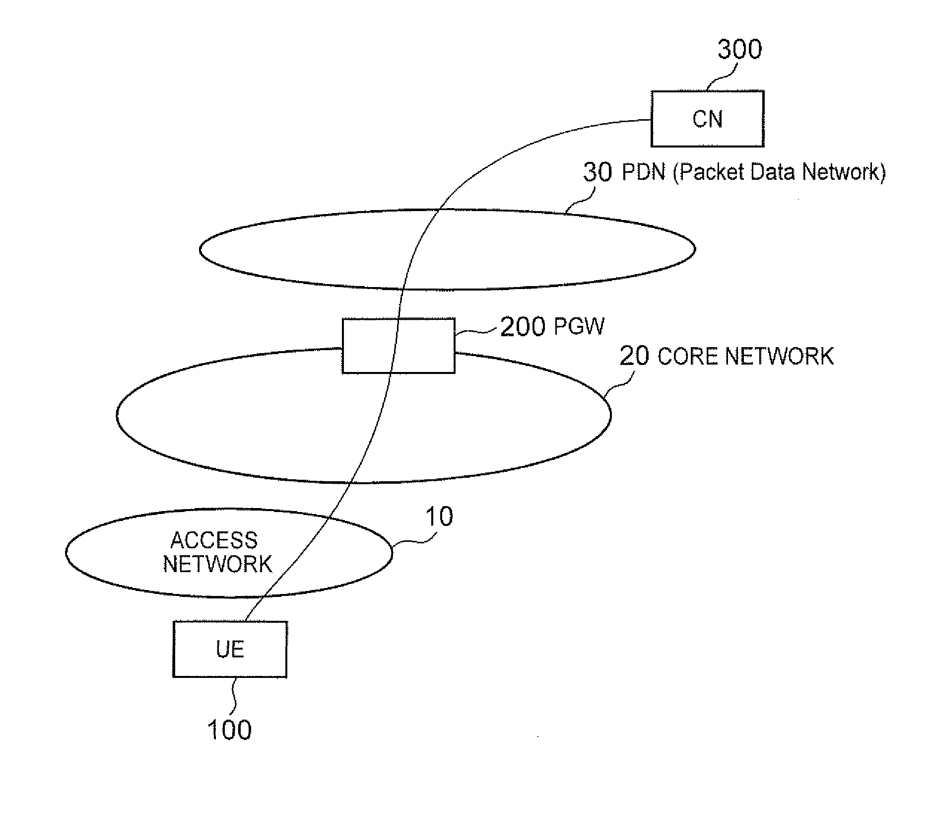
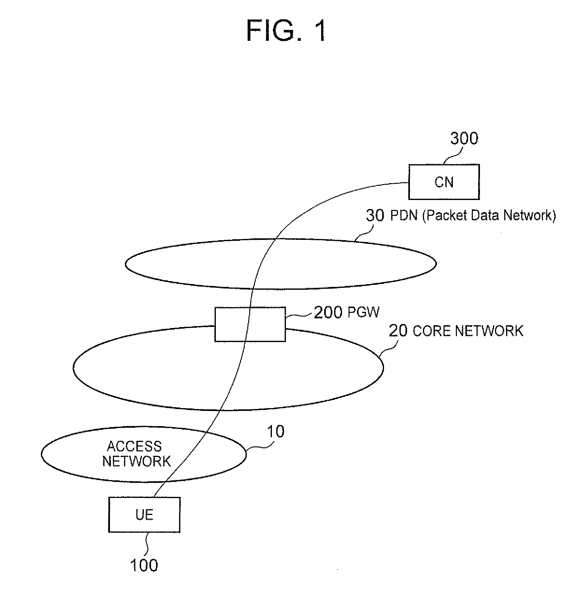
[0114]The operation of a second embodiment of the present invention will be described in detail. FIG. 9 is a diagram for describing a system structure according to the second embodiment of the present invention, including an access network 10, a core network 20, a packet data network (PDN) 30, a mobile terminal (UE) 100 attached to the access network 10 to connect to the PDN 30 via the core network 20, a correspondent node (CN) 300 communicating with the mobile terminal 100 through the PDN 30, a gateway device (PGW: PDN Gateway) 200 for performing connection control when the mobile terminal 100 connects to the PDN 30, a local gateway device (SGW: Serving Gateway) 600 for controlling the PGW 200 to perform local connection control on the mobile terminal 100 to the access network 10, a mobility management entity (MME) 500 for performing mobility management of the mobile terminal 100, and a base station device (eNB: evolved Node B) 400 as a direct attach point of the mobile terminal 10...

third embodiment

[0180]The operation of a third embodiment of the present invention will be described in detail. FIG. 16 is a diagram for describing a system structure according to the third embodiment of the present invention, including an access network 10, a core network 20, a packet data network (PDN) 30, a mobile terminal (UE) 100 attached to the access network 10 to connect to the PDN 30 via the core network 20, a correspondent node (CN) 300 communicating with the mobile terminal 100 through the PDN 30, a gateway device (PGW: PDN Gateway) 200 for performing connection control when the mobile terminal 100 connects to the PDN 30, a local gateway device (SGW: Serving Gateway) 600 for controlling the PGW 200 to perform local connection control on the mobile terminal 100 to the access network 10, a mobility management entity (MME) 500 for performing mobility management of the mobile terminal 100, a mobile base station (RN: Relay Node) 800 as a direct attach point of the mobile terminal 100 to the a...

fourth embodiment

[0213]The operation of a fourth embodiment of the present invention will be described in detail. FIG. 20 is a diagram for describing a system structure according to the fourth embodiment of the present invention, including an access network 10, a core network 20, a packet data network (PDN) 30, a mobile terminal (UE) 100 attached to the access network 10 to connect to the PDN 30 via the core network 20, a correspondent node (ON) 300 communicating with the mobile terminal 100 through the PDN 30, a gateway device (PGW: PDN Gateway) 200 for performing connection control when the mobile terminal 100 connects to the PDN 30, a local gateway device (SGW: Serving Gateway) 600 for controlling the POW 200 to perform local connection control on the mobile terminal 100 to the access network 10, a mobility management entity (MME) 500 for performing mobility management of the mobile terminal 100, a mobile base station (RN: Relay Node) 800 as a direct attach point of the mobile terminal 100 to the...


PUM


Abstract

The present invention discloses a technique for providing a packet recovery method, and the like, capable of starting packet recovery processing without waiting for a wasteful latency (time-out) at a mobile terminal by giving notice of information on a packet discard in a gateway device in real time, thereby enabling improvement in communication quality and communication efficiency. According to the technique, there is provided a packet recovery method for recovering a packet discarded by an intermediate device positioned on a communication path between a mobile terminal and a correspondent node of the mobile terminal among packets exchanged between the mobile terminal and correspondent node, the method including: a step of causing the intermediate device to transmit a discard notification message to the mobile terminal based on information on a communication flow for which transmission of the discard notification message indicating that the packet has been discarded is required; and a step of causing the mobile terminal to transmit the correspondent node a retransmission request message for requesting retransmission of the discarded packet based the discard notification message.

Description

TECHNICAL FIELD[0001]The present invention relates to a packet recovery method, a packet recovery system, and a mobile terminal and an intermediate device used in the method for rapid restoration when packet loss occurs in packet communication.BACKGROUND ART[0002]In conventional mobile communication systems, especially mobile communication systems based on a 3GPP standard, there have been two ways of bandwidth allocation to a data path (here, which is particularly called a bearer in conformity to the 3GPP standard) when a mobile terminal performs packet communication with a correspondent node through a core network. One is to apply GBR (Guaranteed Bit Rate), and a bearer based thereon is called a GBR bearer. The other is not to apply GBR, and a bearer based thereon is called a non-GBR bearer.[0003]The GBR bearer is a bearer to which guaranteed QoS is applied, and guaranteed values related to transmission delay, packet loss, transmission rate, and the like, such as QCI (QoS Class Ide...

Claims


Application Information

Patent Timeline
Patent Type & Authority Applications(United States)
IPC IPC(8): H04L12/26H04L69/40
CPCH04L1/1835H04L1/188H04L69/40H04L65/80H04L65/1026H04W8/30
Inventor IKEDA, SHINKICHISUGIZAKI, RYUJIHIRANO, JUNASO, KEIGOTAMURA, TAKASHI
Owner PANASONIC INTELLECTUAL PROPERTY CORP OF AMERICA
Why Eureka
Try Eureka