Lens barrel and camera including lens barrel

Inactive Publication Date: 2012-07-19
CANON KK
View PDF4 Cites 4 Cited by
  • Summary
  • Abstract
  • Description
  • Claims
  • Application Information

AI Technical Summary

Problems solved by technology

This is because there is a limitation on the dimension of the blade which can be stored in a blade storage portion defined by the difference between the diameter of the lens barrel and the effective optical path range of the optical system.
However, users tend to demand a zoom lens with a high magnification and a short focal length at the wide-angle end.
Thus, since there is concern that the lens may be scratched when the upward bent portion passes on the lens, the upward bent portion is not provided in the range overlapping the front lens surface as viewed on the projection plane.

Method used


Image

  • Lens barrel and camera including lens barrel
  • Lens barrel and camera including lens barrel
  • Lens barrel and camera including lens barrel

Examples


Embodiment Construction

[0031]Various exemplary embodiments, features, and aspects of the invention will be described in detail below with reference to the drawings.

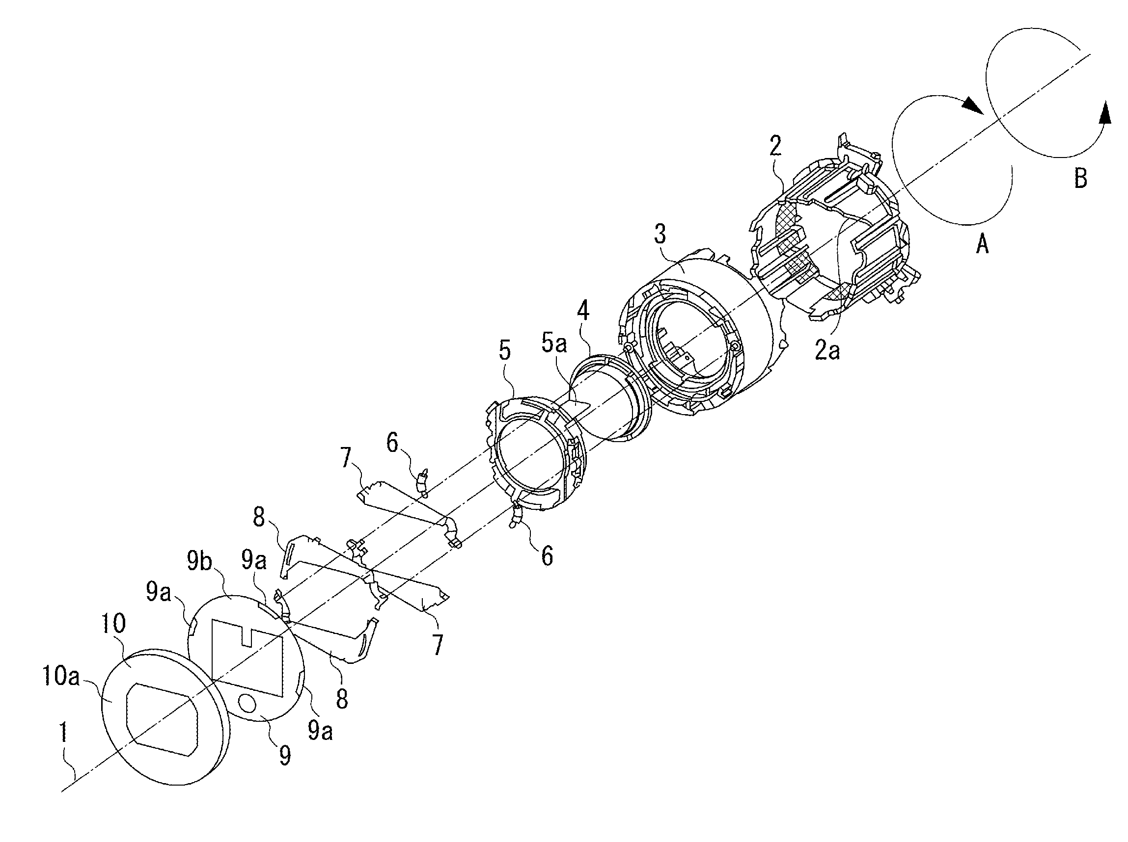
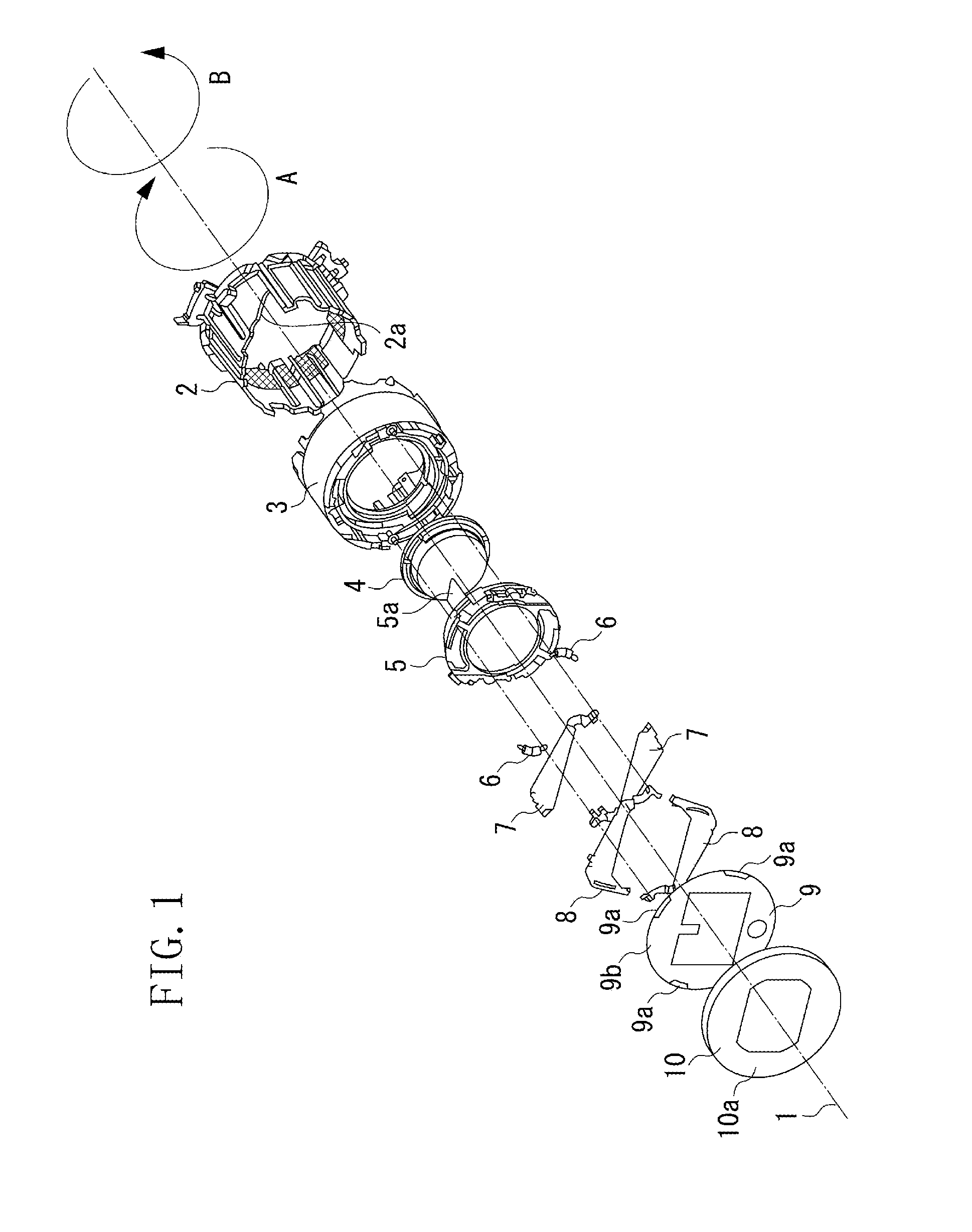
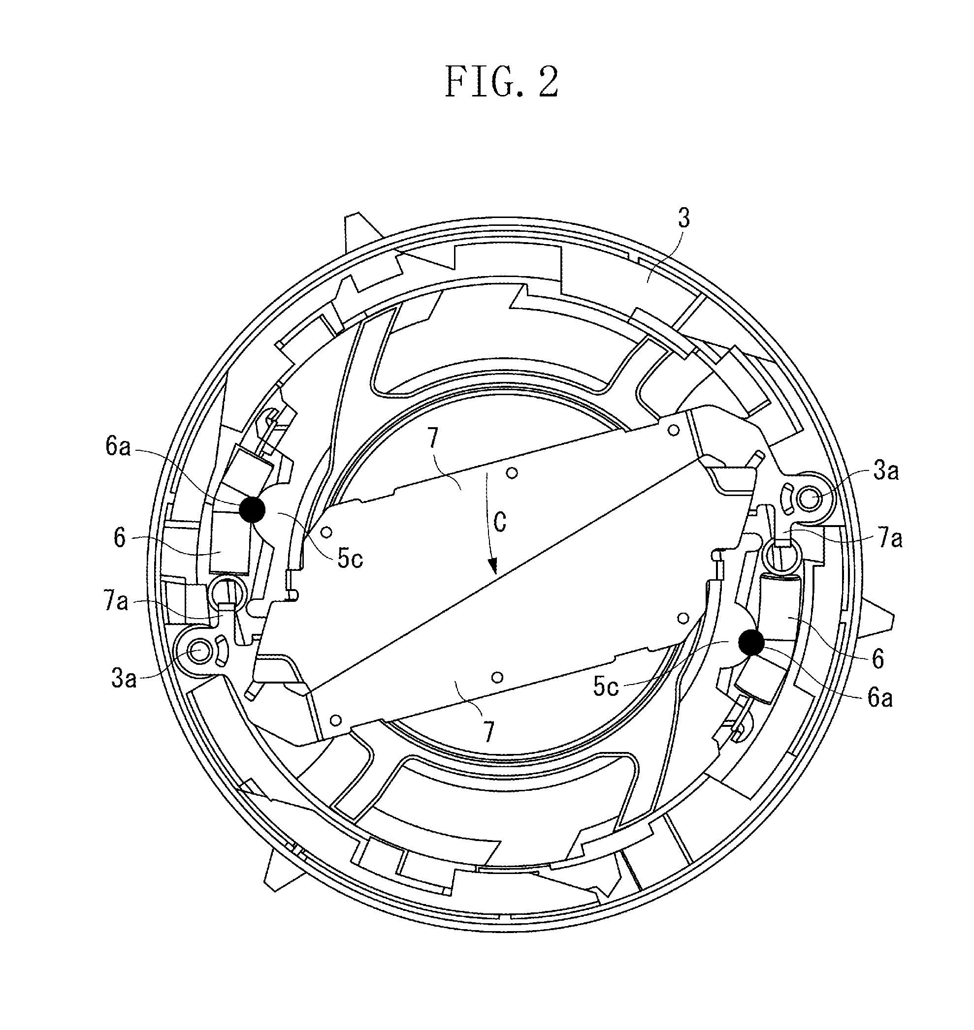
[0032]Referring to FIGS. 1, 2, 3, and 4, a barrier mechanism which is incorporated in a camera according to an exemplary embodiment of the invention will be schematically described.

[0033]FIG. 1 is an exploded perspective view illustrating a barrier mechanism according to an exemplary embodiment of the invention. FIG. 2 is a front view illustrating a state where a barrier is fully closed, FIG. 3 is a front view illustrating a state where the barrier starts to be opened, and FIG. 4 is a front view illustrating a state where the barrier is opened. A lens tube 3 includes a barrier mechanism and is positioned at the front end of the lens barrel when the lens tube 3 switches from a retracted state to a shooting-ready state. The lens tube 3 is configured to switch between the shooting-ready state and the retracted state, and FIG. 4 illustrates the sta...


PUM


Abstract

A lens barrel includes a lens tube configured to hold a lens, a barrier driving member configured to move between an opened state and a closed state by switching of the lens tube between a shooting-ready state and a retracted state, a pair of first barrier blades, each of which includes a blade portion, configured to open and close in conjunction with the barrier driving member, and a pair of second barrier blades, each of which includes a blade portion and a coupling portion, the coupling portion positioned outside the lens as viewed from an object side and located closer to the first barrier blade than the blade portion, the pair of second barrier blades being configured to be moved by contact between the coupling portion and the first barrier blade.

Description

BACKGROUND OF THE INVENTION[0001]1. Field of the Invention[0002]The present invention relates to a lens barrel which includes barrier blades configured to open and close a front surface of a photographic lens, mounted on an imaging apparatus such as a camera, to protect the photographic lens.[0003]2. Description of the Related Art[0004]In a retractable-lens camera, which compactly retracts a lens barrel when the camera is carried and extends the lens barrel to move a photographic lens to an appropriate position when the camera is used, various lens barrier mechanisms have been proposed in which barrier blades cover the front surface of the lens when the lens barrel is in its retracted position and the barrier blades are retracted from the front surface of the lens when the camera is in use.[0005]In such a barrier mechanism, the number of barrier blades which constitute the barrier can be selected depending on the effective optical path range of an optical system and the diameter of ...

Claims


Application Information

Patent Timeline
IPC IPC(8): G03B17/04G02B7/02
CPCG03B9/22G03B17/14G03B17/04
Inventor ISHIMASA, TORU
Owner CANON KK
Why Eureka
Try Eureka