Perforated Nonslip Non-Adhesive Surface Covering

a non-adhesive surface, non-slip technology, applied in the direction of tomography, therapy, patient positioning for diagnostics, etc., can solve the problems of enhancing the hand alteration of the perforated covering, weakening the tear strength properties of the non-slip layer, etc., to achieve the effect of strengthening the dimensional stability of the underling layer

Inactive Publication Date: 2012-07-19
KITTRICH
View PDF5 Cites 2 Cited by
  • Summary
  • Abstract
  • Description
  • Claims
  • Application Information

AI Technical Summary

Benefits of technology

[0028]The disadvantages and limitations of the background art discussed above are overcome by the present invention. With this invention, a removable, nonslip, non-adhesive covering is provided, wherein an improved multilayered composite material having a top decorative layer of polymeric film is combined to a continuous bottom layer of unsupported foam. The structure of the multilayered composite material facilitates the convenient hand tearing of the shelf, drawer or storage liner to size through a grid of perforations oriented along the vertical and horizontal axes of the covering.
[0029]In accordance with the present invention, the composite material includes a top facing layer of polymeric film that reinforces the dimensional stability of the underling layer of unsupported foam. The polymeric film may be combined to the unsupported foam by means of thermal fusion or, alternatively, through the application of an intermediate layer of adhesive. In a specific embodiment, the facing layer may be a polyvinyl chloride sheet, although other synthetic films may be used. The polymeric sheet has sufficient tensile and tear strength properties along the machine and transverse directions of the film to inhibit failure of the multilayered composite material during perforation. The top facing surface of the polyvinyl chloride sheet may be smooth or, more preferably, thermally embossed with a decorative pattern during fusion of the polymeric film to the layer of unsupported foam. By this means, the thermal embossment of the composite material obscures the grid of perforations that penetrate the obverse layer of the shelf, drawer or storage liner.
[0030]The underlying layer of unsupported foam consists of a polymeric compound having a diffusion of minuscule gas bubbles. In a preferred embodiment, the polymeric admixture is a polyvinyl chloride resin that includes a chemical foaming agent. The chemical foaming agent is selected from the group of hydrazine derivatives, and is more particularly an Azodicarbonamide powder that is suspended in the resin formulation. Under thermal decomposition, Azodicarbonamide releases nitrogen when exposed to temperatures in the range of 200° to 215° C., thereby causing the expansion of the polymeric composition. The polyvinyl chloride compound is cured by means of a thermal calendering process, wherein the polymeric admixture is uniformly coated on a releasable belt or casting paper which is compressed against a heated roller. In the absence of a knitted scrim or non-woven fabric substrate, the releasable belt or casting paper provides support and dimensional stability to the unsupported polymeric compound while maintaining the uniform thickness of the nonslip material during solidification. The heated roller, releasable belt or casting paper may be configured to impart a fine pattern of micro-embossed indentations on the bottom surface of the unsupported calendered foam. The micro-embossed indentations essentially weaken the tear strength properties of the nonslip layer and enhance the hand alteration of the perforated covering.

Problems solved by technology

The micro-embossed indentations essentially weaken the tear strength properties of the nonslip layer and enhance the hand alteration of the perforated covering.

Method used


Image

  • Perforated Nonslip Non-Adhesive Surface Covering
  • Perforated Nonslip Non-Adhesive Surface Covering
  • Perforated Nonslip Non-Adhesive Surface Covering

Examples


Embodiment Construction

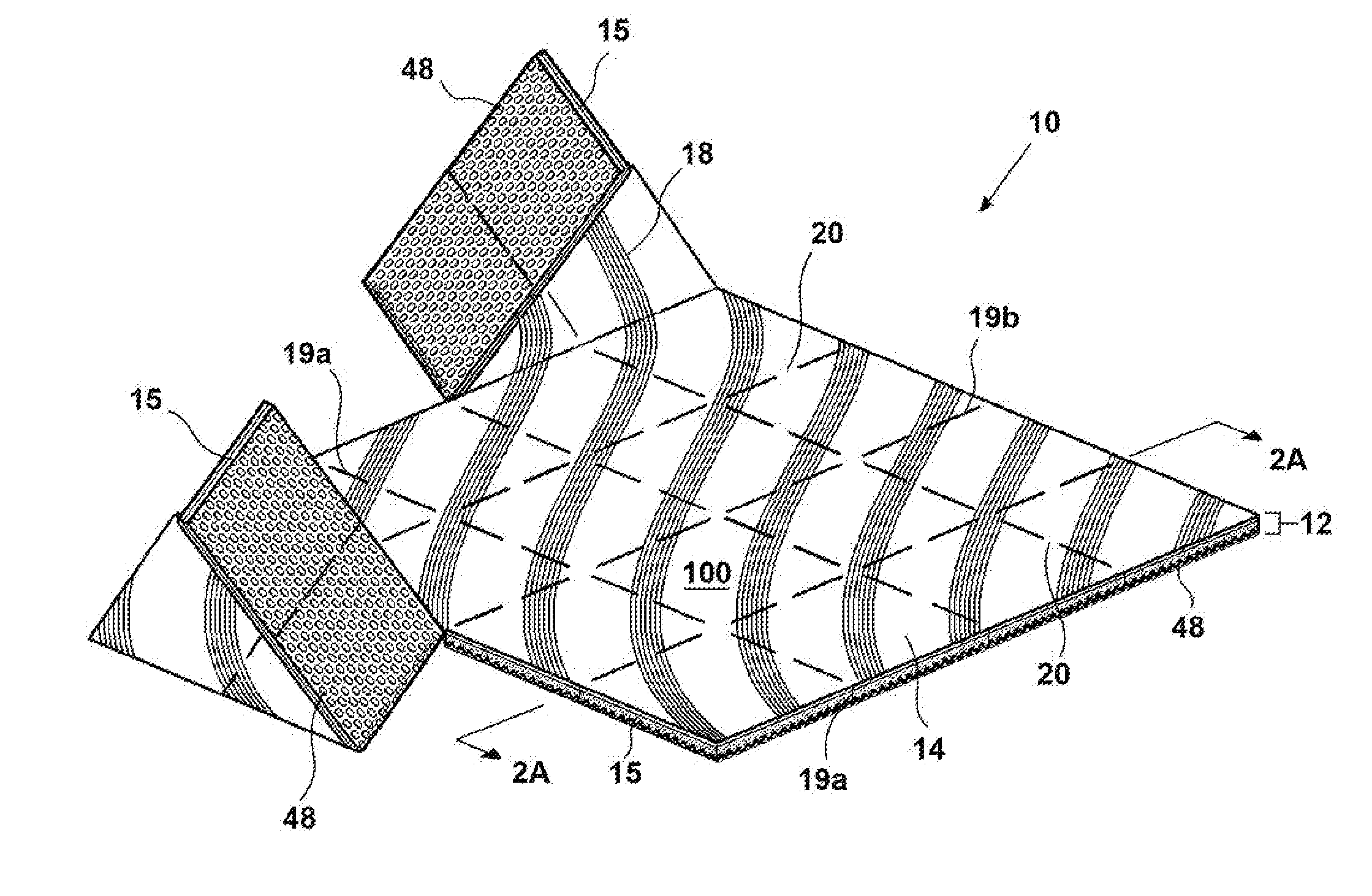
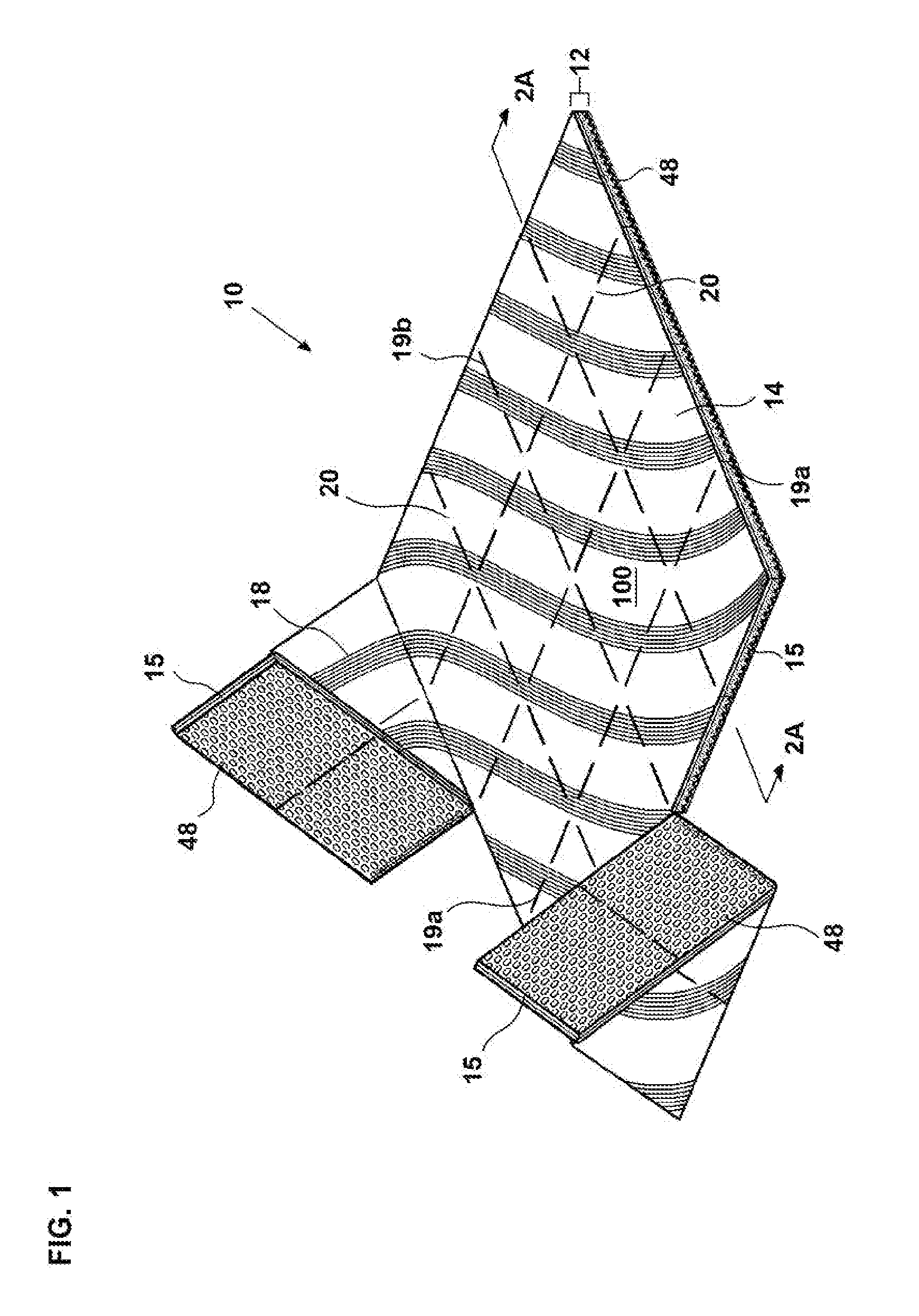
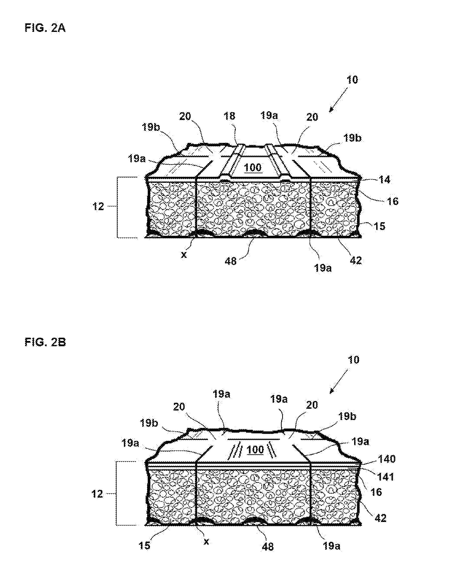
[0043]The present invention is a removable, nonslip, non-adhesive surface covering suitable for use as a shelf, drawer or storage liner, and designated generally as 10 in the drawings. With reference to FIG. 1, the surface covering 10 is a multilayered composite material 12 having a top facing layer of polymeric film 14 combined to a continuous bottom layer of unsupported foam 15. The structure of the multilayered composite material 12 facilitates the convenient hand tearing of the shelf, drawer or storage liner through a grid of perforations 19a and 19b, which are respectively located along the vertical and horizontal axes of the surface covering 10.

[0044]The top facing layer of polymeric film 14 reinforces the dimensional stability of the underling layer of unsupported foam 15. The facing layer 14 may consist of single or multiple layers of thermoplastic film which may be extruded, calendered or cast from the group of polymers that include Polyvinyl Chloride (PVC); Polypropylene (...


PUM

PropertyMeasurementUnit
thicknessaaaaaaaaaa
thicknessaaaaaaaaaa
temperaturesaaaaaaaaaa

Abstract

A surface covering that is a multilayered composite material. The multilayer composite material includes a top facing layer of polymeric film and a bottom layer of unsupported foam.

Description

RELATED APPLICATION DATA[0001]The present application claims priority to provisional application 61 / 432906 filed in the United States Patent Office on Jan. 14, 2011, the entirety of which is hereby incorporated by reference herein to the extent permitted by law.BACKGROUND OF THE INVENTION[0002]1. Field of the Invention[0003]The present invention is directed to removable, nonslip, non-adhesive coverings which are used as shelf, drawer or storage liners. In particular, the covering sheet features an improved composite material having a top decorative layer of polymeric film combined to a continuous bottom layer of unsupported foam. The structure of the multilayered composite material facilitates the convenient hand tearing of the sheet to size through a grid of perforations oriented along the vertical and horizontal axes of the covering.[0004]2. Description of the Prior Art[0005]Shelf, drawer or storage liners have been extensively sold at retail venues and are available in a selectio...

Claims


Application Information

Patent Timeline
Patent Type & Authority Applications(United States)
IPC IPC(8): B32B5/18B29C65/54B32B27/00B32B38/06B32B38/04B32B3/30B29C65/02B29C59/00
CPCA61B6/032A61B6/0457A61B6/405A61B6/4085A61B6/481A61B6/482Y10T428/24322A61B6/541A61N5/103A61N5/1039Y10T156/1057Y10T156/1041Y10T428/24496A61B6/507B32B3/266B32B3/30B32B27/065B32B27/304B32B37/06B32B37/12B32B38/04B32B38/06B32B38/1875B32B2038/0084B32B2038/045B32B2038/047B32B2266/02B32B2266/0214B32B2266/0235B32B2266/0278B32B2305/022B32B2307/744B32B7/14B32B27/12B32B2262/02Y10T428/249953Y10T428/249982Y10T428/249987Y10T428/249992Y10T428/249993B32B5/18B32B7/12Y10T428/15Y10T428/24504Y10T428/24851Y10T428/24995Y10T428/249985Y10T428/249991A61B6/0487B32B2266/0207B32B2266/0221B32B29/007B32B2479/00A61B6/04A61B6/4275A61M5/007A61N5/1037
Inventor CALKINS, MARK A.
Owner KITTRICH
Why Eureka
Try Eureka