Control computer and method of controlling robotic arm

a robotic arm and computer technology, applied in the field of automatic measurement technology, can solve problems such as non-linear movement of robotic arms and introduction of measurement errors

Inactive Publication Date: 2012-07-19
HON HAI PRECISION IND CO LTD
View PDF5 Cites 8 Cited by
  • Summary
  • Abstract
  • Description
  • Claims
  • Application Information

AI Technical Summary

Problems solved by technology

However, the robotic arms are driven by motors and therefore the movements of the robotic arms are non-linear.
Therefore, controlling the movements of the robotic arms based on the coordinate information recorded in the layout files of the PCBs may introduce measurement errors.

Method used


Image

  • Control computer and method of controlling robotic arm
  • Control computer and method of controlling robotic arm
  • Control computer and method of controlling robotic arm

Examples


Embodiment Construction

[0009]The disclosure, including the accompanying drawings in which like references indicate similar elements, is illustrated by way of examples and not by way of limitation. It should be noted that references to “an” or “one” embodiment in this disclosure are not necessarily to the same embodiment, and such references mean at least one.

[0010]In general, the word “module”, as used herein, refers to logic embodied in hardware or firmware, or to a collection of software instructions, written in a programming language, such as, Java, C, or assembly. One or more software instructions in the modules may be embedded in firmware, such as in an EPROM. The modules described herein may be implemented as either software and / or hardware modules and may be stored in any type of non-transitory computer-readable medium or other storage device. Some non-limiting examples of non-transitory computer-readable media include CDs, DVDs, BLU-RAY, flash memory, and hard disk drives.

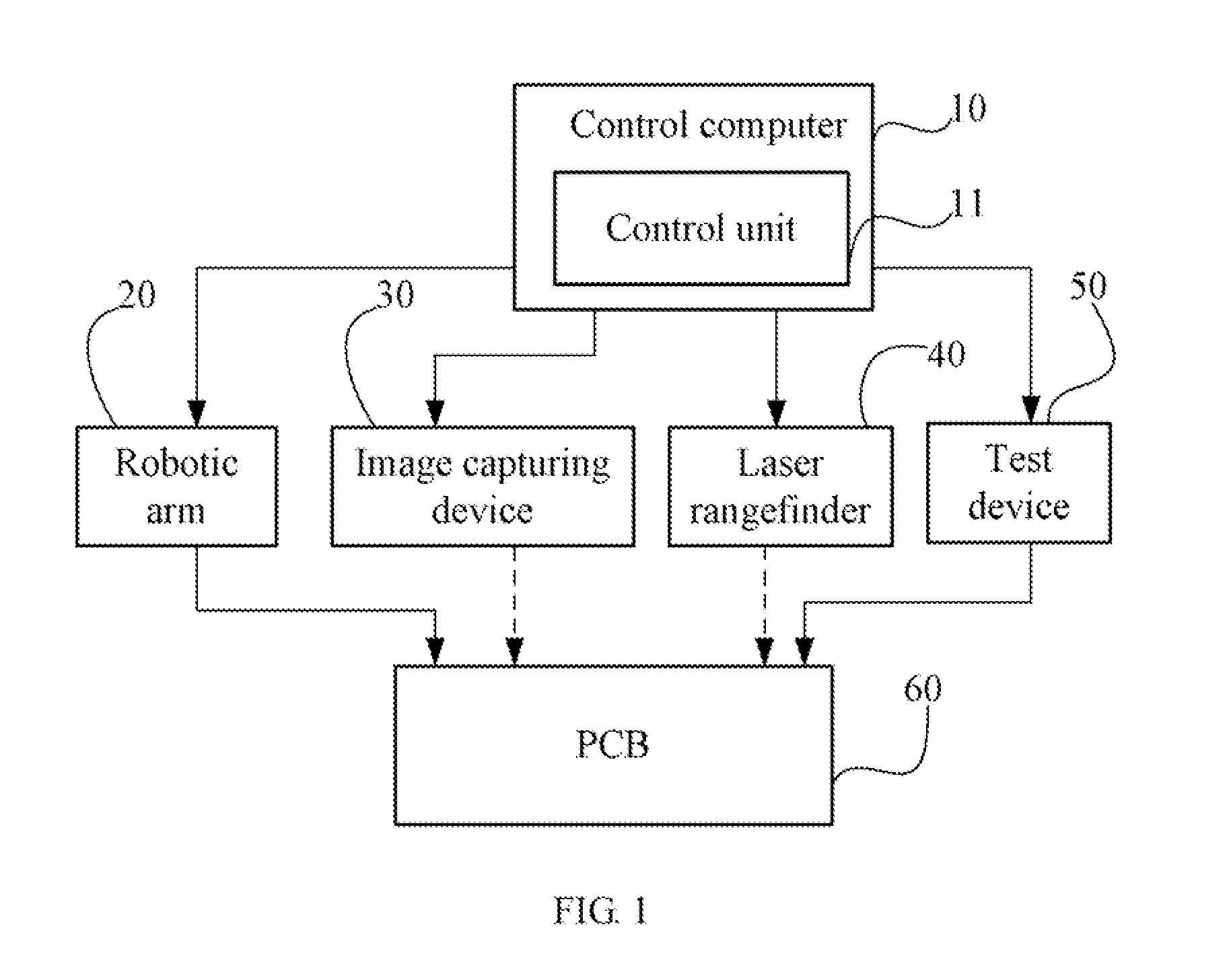
[0011]FIG. 1 is a block d...


PUM


Abstract

A computer determines a first origin of a first coordinate system of a PCB, and controls a robotic arm to position a probe above the first origin. Furthermore, the computer determines a second origin of a second coordinate system of the robotic arm, and determines displacement values from the first origin to a test point in controlling movements of the robotic arm in the second coordinate system. A graph representing the test point is recognized in an image of the PCB, pixel value differences between the graph center and the image center are determined and converted to displacement correction values for controlling the movements of the robotic arm and determining 3D coordinates of the test point. The robotic arm is moved along a Z-axis of the second coordinate system to precisely position the probe on the test point of the PCB.

Description

BACKGROUND[0001]1. Technical Field[0002]The present disclosure relates to automatic measurement technology, and particularly to a control computer and a method of controlling a robotic arm.[0003]2. Description of Related Art[0004]In printed circuit board (PCB) inspection, robotic arms are commonly used to automatically position test tools (e.g., probes) on test points of PCBs based on coordinate information recorded in layout files of the PCBs. In such a test manner, the test points are regarded as pure points having no size, and the coordinate information recorded in the layout files arise from linear coordinates systems of the PCBs. However, the robotic arms are driven by motors and therefore the movements of the robotic arms are non-linear. On another hand, the test points on the PCBs are often small parts (e.g., a pad) having sizes, but are not pure points. Therefore, controlling the movements of the robotic arms based on the coordinate information recorded in the layout files o...

Claims


Application Information

Patent Timeline
Patent Type & Authority Applications(United States)
IPC IPC(8): B25J9/10
CPCG05B19/4015B25J9/1679
Inventor LI, SHEN-CHUNLIANG, HSIEN-CHUANHSU, SHOU-KUO
Owner HON HAI PRECISION IND CO LTD
Why Eureka
Try Eureka