Power feeding device and wireless power feeding system

a technology of wireless power transmission and power feeding device, which is applied in the direction of circuit arrangement, inductance, amplitude demodulation details, etc., can solve the problems of increasing the size and cost of the device, and achieve the effect of high power transmission efficiency

Active Publication Date: 2012-07-26
SEMICON ENERGY LAB CO LTD
View PDF1 Cites 31 Cited by
  • Summary
  • Abstract
  • Description
  • Claims
  • Application Information

AI Technical Summary

Benefits of technology

[0018]One embodiment of the present invention can provide a resonant power feeding system that can provide high power transmission efficiency between a power feeding device an...

Problems solved by technology

This leads to the increase...

Method used


Image

  • Power feeding device and wireless power feeding system
  • Power feeding device and wireless power feeding system
  • Power feeding device and wireless power feeding system

Examples


embodiment 1

[0033]In this embodiment, a resonant wireless power feeding system according to one embodiment of the present invention will be described.

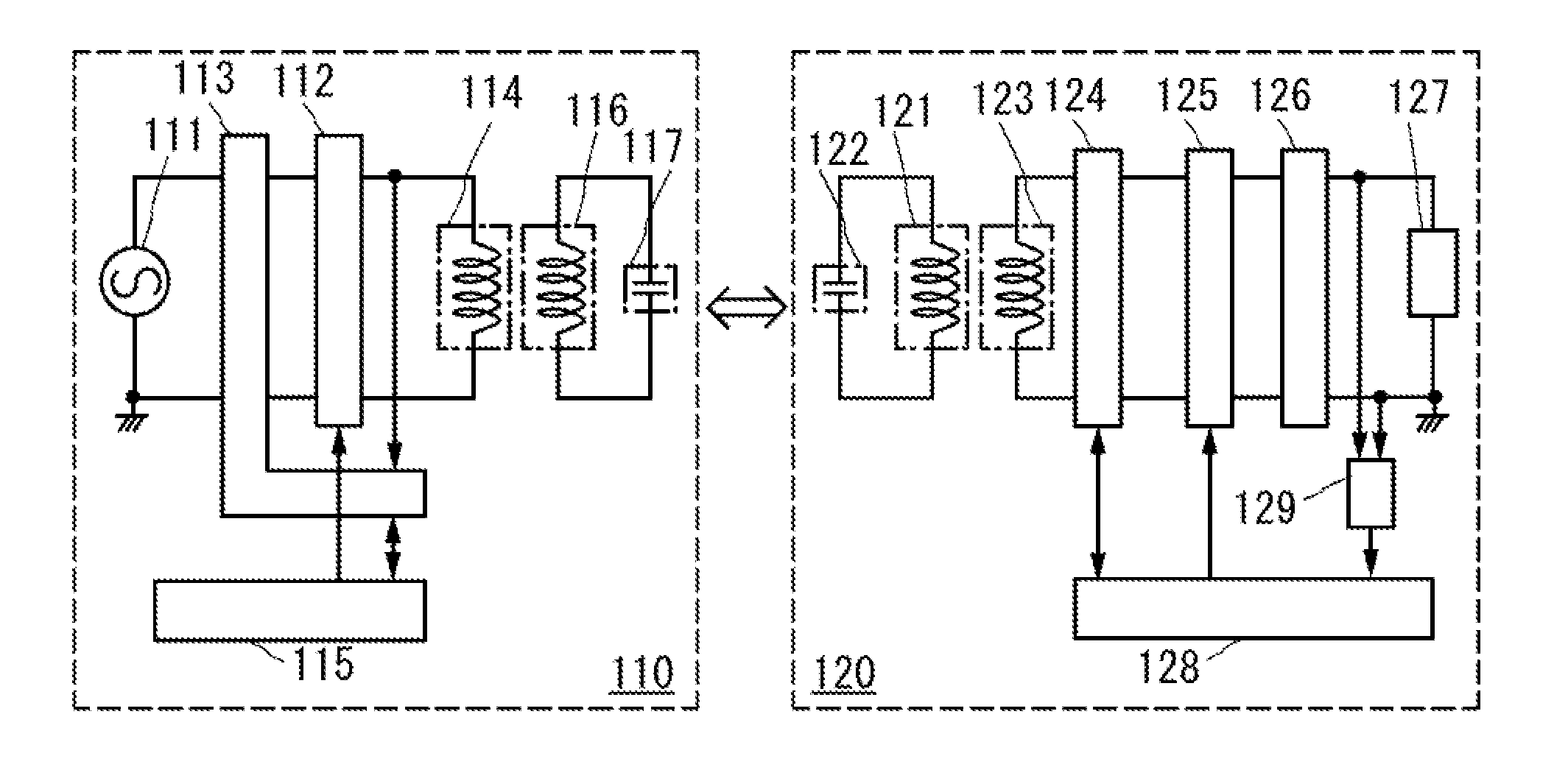
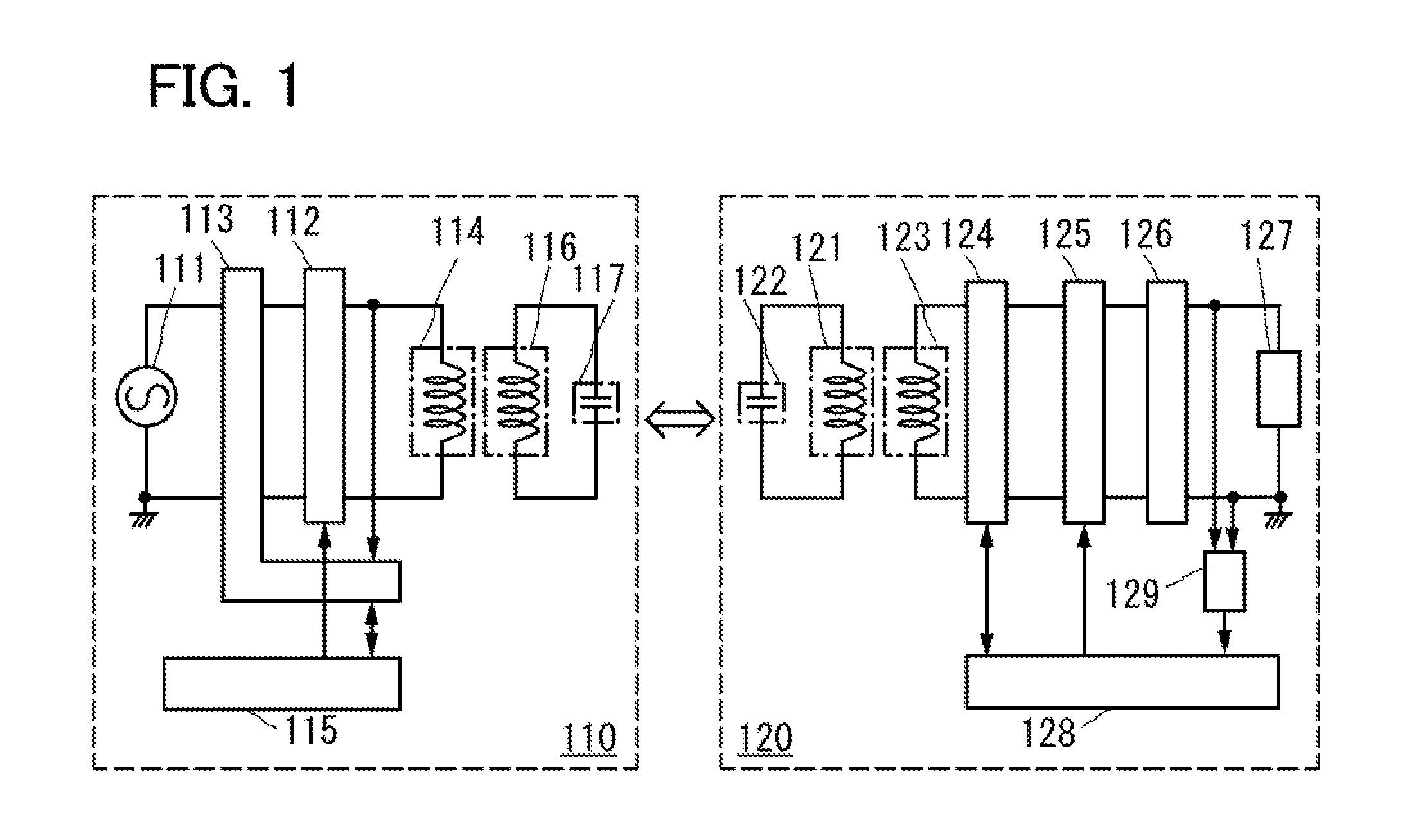
[0034]FIG. 1 is a block diagram of a power feeding device and a power reception device. FIG. 1 illustrates power transmission with an electromagnetic field using resonance of a first resonant coil in the power feeding device and a second resonant coil in the power reception device. In the block diagram in FIG. 1, circuits in the power feeding device and the power reception device are classified according to their functions and shown as independent units. Note that it is difficult to completely separate circuits in accordance with functions in an actual power feeding device and an actual power reception device. It is possible that one circuit has a plurality of functions or a plurality of circuits achieve a function corresponding to one unit.

[0035]A power feeding device 110 includes a high frequency power source 111, a first matching circuit 112, a...

embodiment 2

[0096]In this embodiment, applications of the wireless power feeding system described in Embodiment 1 will be described. Examples of applications of the wireless power feeding system according to one embodiment of the present invention are portable electronic devices, such as a digital video camera, a portable information terminal (e.g., a mobile computer, a mobile phone, a portable game machine, and an e-book reader), and an image reproducing device including a recording medium (specifically a digital versatile disc (DVD)). In addition, an electric propulsion vehicle that is powered by electric power, such as an electric car, can be given. Examples will be described below with reference to drawings.

[0097]FIG. 7A illustrates an example of an application of the wireless power feeding system to a mobile phone and a portable information terminal. A power feeding device 701, a mobile phone 702A including a power reception device 703A, and a mobile phone 702B including a power reception ...


PUM


Abstract

A resonant power feeding system that can provide high power transmission efficiency between a power feeding device and a power reception device without dynamically controlling the oscillation frequency in accordance with the distance between the power feeding device and the power reception device. High power transmission efficiency between the power feeding device and the power reception device is obtained by addition of a structure for adjusting the matching condition to both the power reception device and the power feeding device. Specifically, a transmission-reception circuit and a matching circuit are provided in both the power reception device and the power feeding device, and wireless signals for adjusting the matching circuit are transmitted and received through a resonant coil. Thus, the power feeding device can efficiently supply power to the power reception device without adjusting the oscillation frequency.

Description

BACKGROUND OF THE INVENTION[0001]1. Field of the Invention[0002]The present invention relates to power feeding devices and wireless power feeding systems including the power feeding devices.[0003]2. Description of the Related Art[0004]A variety of electronic devices have spread, and a wide range of products are shipped to the market. In recent years, portable electronic devices such as mobile phones and digital video cameras have spread widely. Further, electric propulsion vehicles that are powered by electric power, such as electric cars, are coming on the market as products.[0005]Mobile phones, digital video cameras, and electric propulsion vehicles include batteries which are energy storage means. At the moment, the batteries are charged in most cases by being directly connected to home AC sources which are power feeding means. Other devices that have no battery or do not use power charged in a battery are directly supplied with power from a home AC source through a wiring or the...

Claims


Application Information

Patent Timeline
IPC IPC(8): H02J17/00
CPCH02J7/025H02J50/12H02J50/80H02J50/90H02J50/40H01F38/14H03C1/36H03D1/02H03H7/38H02J50/005H04B5/0037H01F2038/146
Inventor KAMATA, KOICHIROOKANO, SHINYASATO, MISAKOMAEDA, SHUHEI
Owner SEMICON ENERGY LAB CO LTD
Why Eureka
Try Eureka