Inkjet print apparatus and inkjet control method

Active Publication Date: 2012-07-26
CANON KK
View PDF1 Cites 11 Cited by
  • Summary
  • Abstract
  • Description
  • Claims
  • Application Information

AI Technical Summary

Benefits of technology

[0009]Taking the problems above into consideration, the object of the present invention is to provide an inkjet print apparatus that is capable of suppressing the amount of wasted ink used for dissolving accumulated adhering ink in the portion where preliminary ejection is performed.
[0011]With the construction described above, as the elapsed time of the previous operation becomes longer, the number of times preliminary ejection is performed in order to dissolve adhering ink in the ink receiving unit is increased. As a result, it is possible to suppress the amount of ink that is used for dissolving adhering ink that accumulates in the portion where preliminary ejection is performed.

Problems solved by technology

The amount of ink that is used in one preliminary ejection during the printing operation is a small amount, so in the place where the collected ink is held, the ink accumulates over a comparatively long period of time.
The accumulated ink is ejected into a waste ink tank by a suction means, however, during the suction means, if suction is performed when there is not a sufficient level of ink inside the absorber, air is sucked in and ink remains in the place where the collected ink is held.
However, problems may occur such as ink that has adhered by using the ink over a long period of time accumulating and blocking the ink flow path, causing the ink in the portion where the preliminary ejection is performed to overflow, or the accumulated ink on the absorber being transferred to the face surface, causing poor ink ejection or misdirection to occur.
Moreover, this accumulated ink is difficult to remove and it may become necessary to disassemble and clean the print apparatus, which in that case requires a lot of work and time.
However, the technology disclosed in Japanese Patent Laid-Open No. 2002-052744 does not estimate to what extent the ink has adhered (accumulated), so it is necessary to reduce the adhering ink by performing this preliminary ejection until the cap become nearly full, and then sucking the ink by the suction means.
Therefore, a large amount of ink is used, so wasted ink increases, and the running cost may become high.

Method used


Image

  • Inkjet print apparatus and inkjet control method
  • Inkjet print apparatus and inkjet control method
  • Inkjet print apparatus and inkjet control method

Examples


embodiment 1

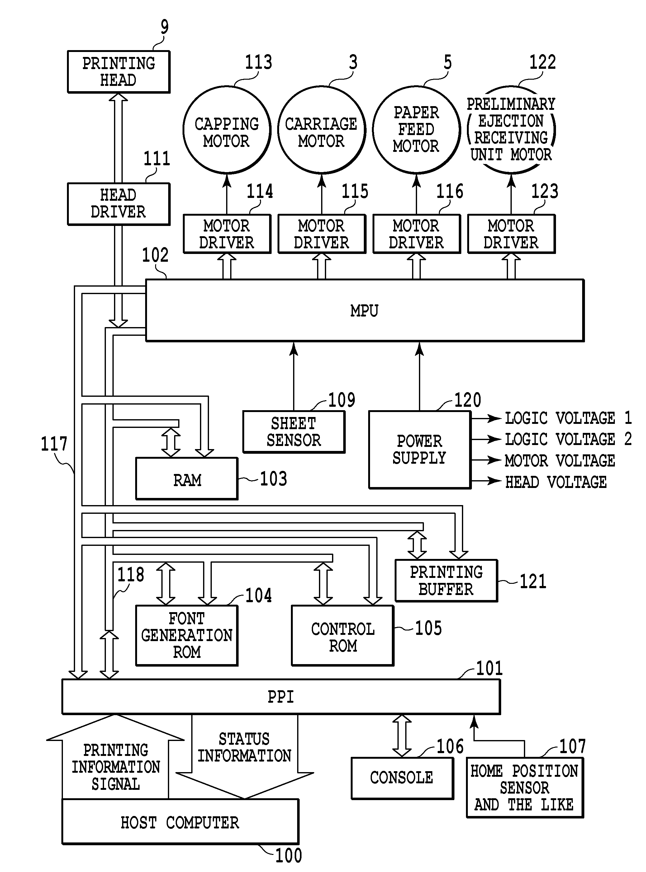
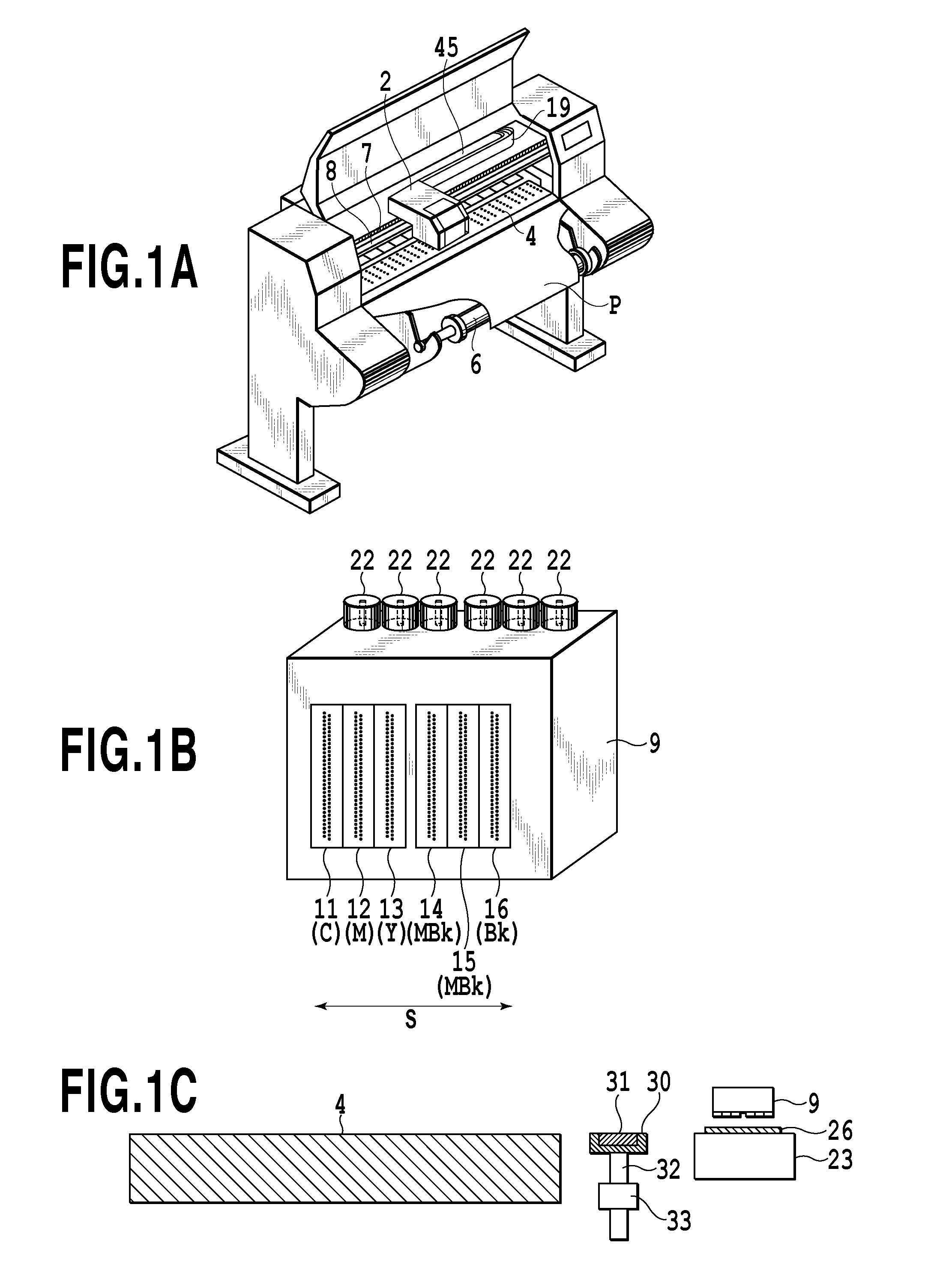
[0028]FIG. 1A is a simplified drawing illustrating the inkjet print apparatus of this first embodiment of the present invention. The inkjet print apparatus of this embodiment is a so-called serial-scan type print apparatus, and forms an image by scanning (main scan) with the printing head in a direction (main scanning direction) that is orthogonal to the conveyance direction of the printing medium P.

[0029]When performing printing, a printing medium P is conveyed by a spool 6 that holds the printing medium P by a paper feeding roller (not illustrated in the figure) that is driven by way of a paper feeding motor via a gear (not illustrated in the figure). At a specified conveyance position a carriage motor (not illustrated in the figure) causes a carriage unit to scan along a guide shaft 8 that extends in a direction that is orthogonal to the conveyance direction. In this scanning process, at timing that is based on a position signal that is obtained by an encoder 7, an ejection opera...

embodiment 2

[0056]In the first embodiment, the amount of time that elapses from the suction means at the end of the previous printing operation is measured, and as that elapsed time increases, either one or both of an increase in the number of preliminary ejections in order to re-dissolve the ink, and strengthening the suction force in the ink receiving unit was performed. However, the present invention can also control the preliminary ejection count threshold value and the ink suction force in the ink receiving unit by taking into consideration the effect on state of ink adhering in the ink receiving unit due to a cause other than the amount of time that elapses from the suction means at the end of the previous printing operation.

[0057]In this embodiment, the effect on the advancement of the state of adhering ink due to the “operating environment of the print apparatus” is taken into consideration in addition to the time count from the suction means at the end of the previous printing operatio...

embodiment 3

[0064]In this embodiment, a recovery control procedure comprising the recovery control procedure of the first embodiment explained using FIG. 5 to which an operation of closing part of the ink flow path is added is explained. In this embodiment, preliminary ejection is performed each scan, and the suction means is performed during the printing operation and after the printing operating is finished.

[0065]FIG. 8 is a flowchart illustrating the control procedure of the printing operation of this embodiment. Here, only the points that differ from the printing operation of the first embodiment explained using FIG. 5 are explained.

[0066]In this embodiment, the time count from the suction means at the end of the previous printing operation is read, and when this time count exceeds 1 hour, selection of the preliminary ejection count threshold value DL (step S47) and selection of the suction pump speed SP (step S48) are performed. Then, after that, an operation (step S49) to close the ink fl...


PUM


Abstract

When performing at least one of preliminary ejection or a suction unit as a countermeasure against adhering ink that accumulates in the portion where preliminary ejection is performed, the preliminary ejection amount and suction speed of the suction unit are optimized. An inkjet print apparatus that prints by using a printing head for ejecting ink, comprising: an ejecting unit; a sucking unit; a measuring unit that measures an elapsed time after the sucking unit is performed; and a control unit that control ejection by the ejecting unit or sucking by the sucking unit according to the elapsed time measured in the measuring unit; wherein as the elapsed time becomes longer, the amount of ink that is ejected to the ink receiving unit in the ejecting unit is increased or a suction speed at which the ink is sucked in the sucking unit is increased.

Description

BACKGROUND OF THE INVENTION[0001]1. Field of the Invention[0002]The present invention relates to a control method for an inkjet print apparatus and to an inkjet print apparatus, and more particularly to a control method of removing ink from an ink receiving unit for receiving ink that has been preliminary ejected.[0003]2. Description of the Related Art[0004]In an inkjet print apparatus, the place where preliminary ink ejection is performed in order to recover the printing head is usually inside a cap that seals the ejection surface (hereafter, is called the face surface) of the printing head when performing suction-based recovery, or is a specially provided ink receiving unit that has a suction unit. In this place, normally an absorber or the like is provided that holds collected ejected ink.[0005]The amount of ink that is used in one preliminary ejection during the printing operation is a small amount, so in the place where the collected ink is held, the ink accumulates over a comp...

Claims


Application Information

Patent Timeline
IPC IPC(8): B41J29/393
CPCB41J2/16538B41J29/38B41J2/16547
Inventor IBE, TSUYOSHIUETSUKI, MASAYASUZUKI, KAZUODANZUKA, TOSHIMITSUKATO, MASATAKATOMIDA, ASAKOKOMATSU, HIROAKI
Owner CANON KK
Why Eureka
Try Eureka