Optical System for Use in a Vehicle Head-Up Display

a head-up display and optical system technology, applied in optics, optical elements, instruments, etc., can solve the problems of reducing the head-up display becomes too big, and the effect of enhancing the definition and discrimination of the drive information imag

Active Publication Date: 2012-07-26
KOREA INST OF CIVIL ENG & BUILDING TECH +1
View PDF2 Cites 20 Cited by
  • Summary
  • Abstract
  • Description
  • Claims
  • Application Information

AI Technical Summary

Benefits of technology

[0019]With the optical system of the present invention, the drive information image projected from the display panel is reflected many times by the first through third pre-lens reflection mirrors to travel an extended distance before it reaches the lens array. This makes it possible to increase the effective length between the display panel and the lens array without having to arrange the display panel and the lens array far away from each other. Consequently, it is possible to increase the depth of the drive information image formed on the windshield and to enhance the definition and discrimination of the drive information image.
[0020]In addition, the drive information image adjusted by the lens array is reflected many times by the first and second post-lens reflection mirrors to travel an extended distance before it reaches the windshield. This makes it possible to increase the focal length between the lens array and the windshield without having to arrange the lens array and the windshield far away from each other. As a consequence, it is possible to increase the depth of the drive information image formed on the windshield and to enhance the definition and discrimination of the drive information image.

Problems solved by technology

This poses a problem in that the depth of the drive information image appearing on the windshield 19 becomes too small, which in turn impairs the definition and discrimination of the drive information image observed by a driver.
This tends to sharply reduce the definition and discrimination of the drive information image.
In this case, however, the size of the head-up display becomes too big, consequently making it difficult to install the head-up display within the instrument panel 10a.

Method used


Image

  • Optical System for Use in a Vehicle Head-Up Display
  • Optical System for Use in a Vehicle Head-Up Display
  • Optical System for Use in a Vehicle Head-Up Display

Examples


Embodiment Construction

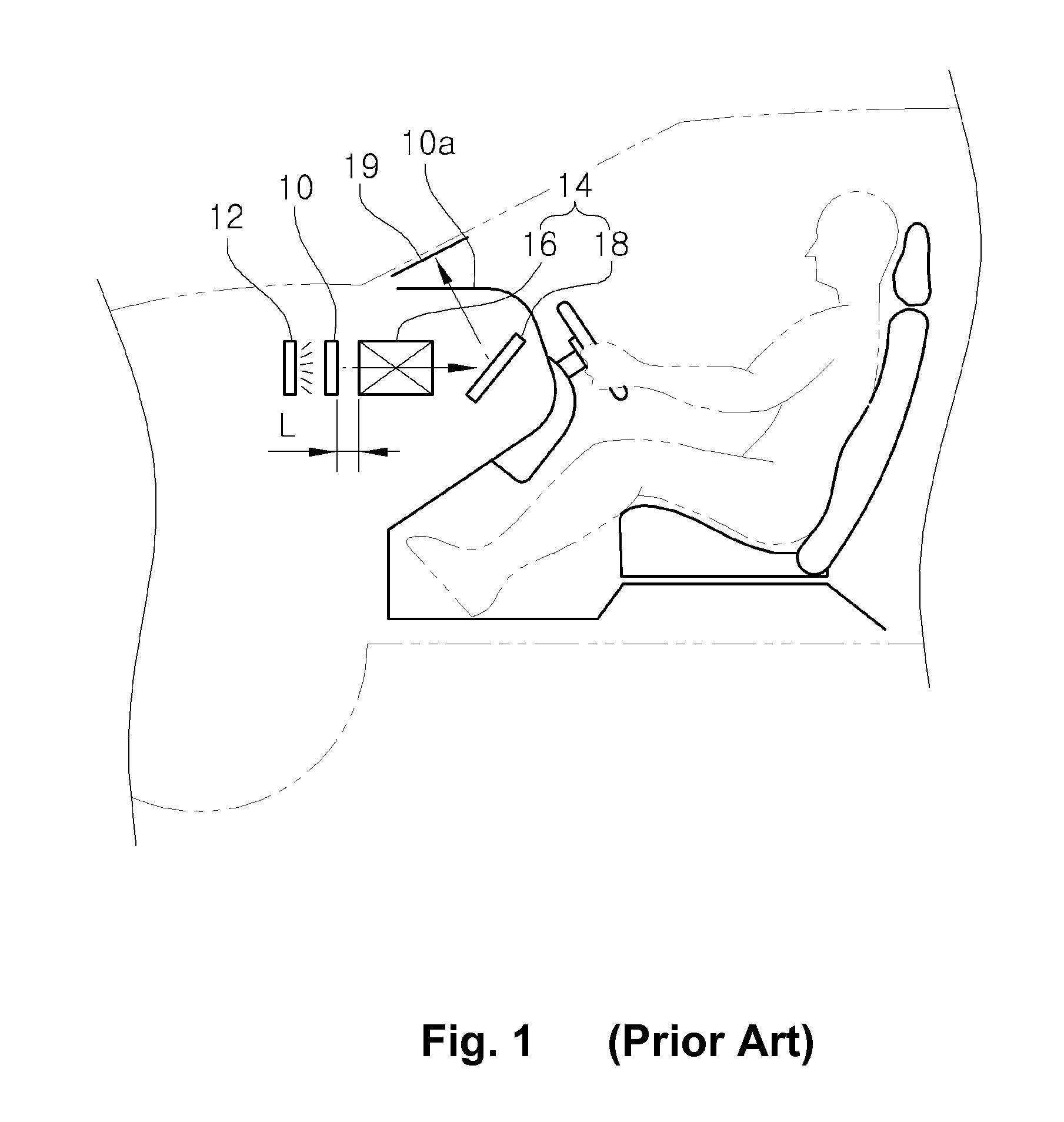
[0026]One preferred embodiment of an optical system for use with a vehicle head-up display will now be described in detail with reference to the accompanying drawings. The same components as those of the conventional head-up display shown in FIG. 1 will be designated by the same reference numerals.

[0027]Brief description on a vehicle head-up display will precede the description of the optical system for use in a vehicle head-up display according to one embodiment of the present invention.

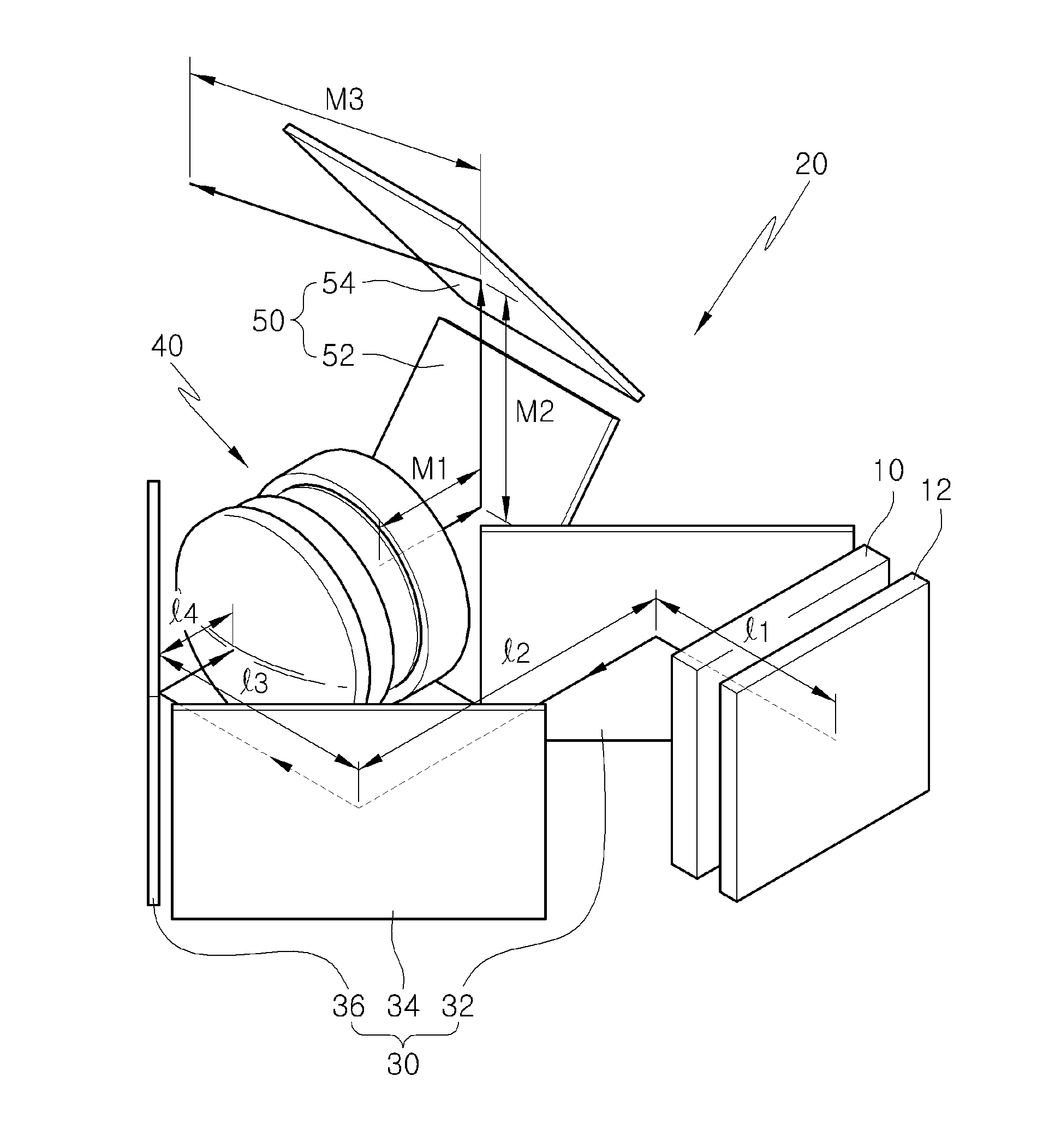
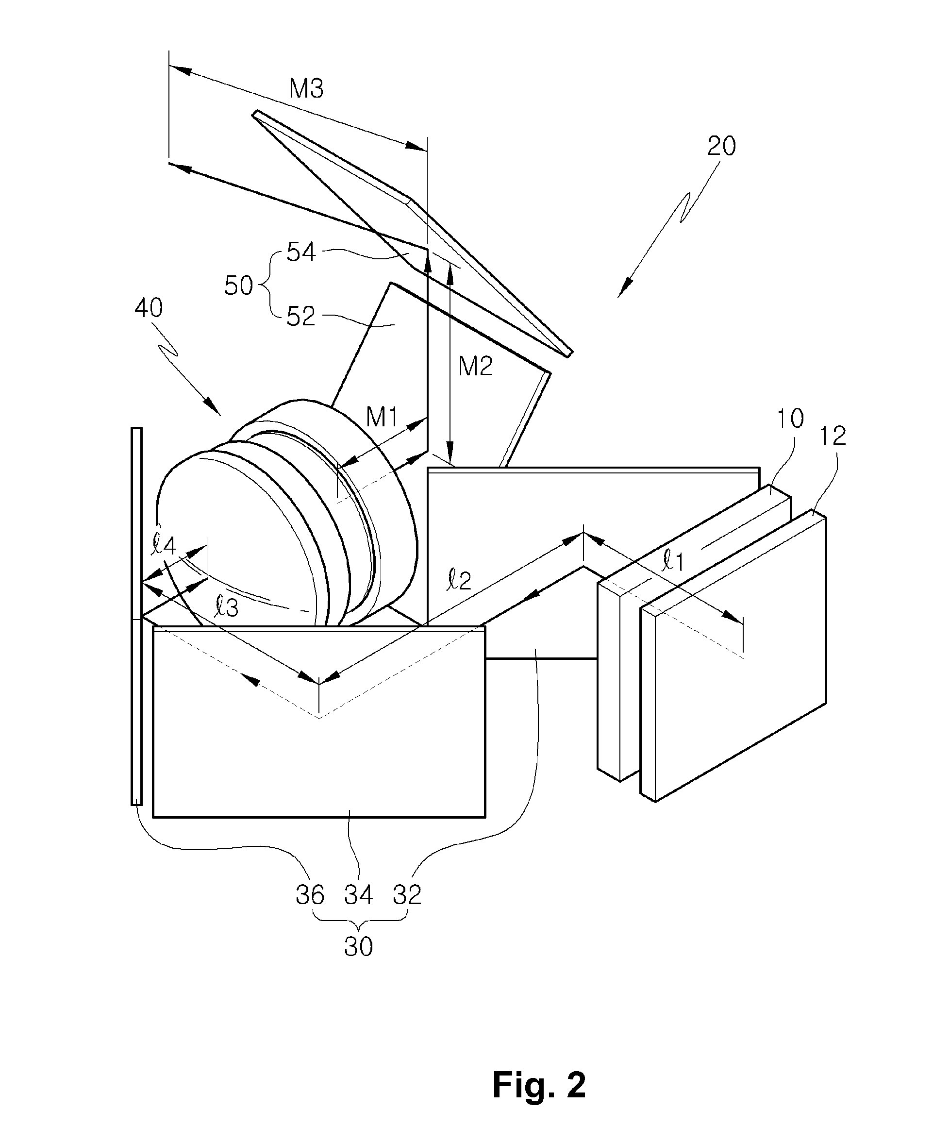
[0028]As described earlier in connection with FIG. 1, the vehicle head-up display includes a display panel 10 and a backlight unit 12 arranged at the rear side of the display panel 10. The display panel 10 is installed inside of an instrument panel 10a in front of a driver seat so that it can display a drive information image. The backlight unit 12 serves as a light source for irradiating light on the rear surface of the display panel 10. The display panel 10 may be one of a liquid crystal display, ...


PUM


Abstract

An optical system is provided for use in a vehicle head-up display including a display panel for displaying drive information image, a backlight unit for irradiating light toward the display panel and an optical system for adjusting the size and focal distance of the drive information image projected from the display panel toward a windshield of a motor vehicle. The optical system includes a pre-lens reflection mirror array for reflecting the drive information image projected from the display panel to travel along a first roundabout path, a lens array for adjusting the size and focal distance of the drive information image reflected by the pre-lens reflection mirror array, and a post-lens reflection mirror array for reflecting the drive information image coming from the display panel toward the windshield to travel along a second roundabout path.

Description

CROSS-REFERENCE TO RELATED APPLICATION[0001]This application claims the benefit of U.S. Provisional Patent Application Ser. No. 61 / 436,516, filed on Jan. 26, 2011, which application is incorporated herein by reference in its entirety.FIELD OF THE INVENTION[0002]The present invention relates to an optical system for use in a vehicle head-up display, capable of enhancing the definition and discrimination of a drive information image formed on the windshield of a motor vehicle.BACKGROUND OF THE INVENTION[0003]In recent years, various kinds of devices have been developed in an effort to enhance the driver's convenience and the safe driving. One example of such devices is a head-up display (HUD) for motor vehicles. The head-up display is designed to display a variety of drive information, e.g., a vehicle speed, a revolution per minute and a residual fuel amount, on the windshield of a vehicle.[0004]A flat-panel-type head-up display is primarily used as the head-up display for motor vehic...

Claims


Application Information

Patent Timeline
Patent Type & Authority Applications(United States)
IPC IPC(8): G02B27/01
CPCG02B2027/0127G02B27/0101
Inventor KANG, WEON EUIMOON, BYEONG SUPPARK, BUM JINLIM, HYUK KYUCHOI, SEOK JAE
Owner KOREA INST OF CIVIL ENG & BUILDING TECH
Why Eureka
Try Eureka