Clamping jig, a friction testing device having the clamping jig, and friction test method

a technology of friction testing and clamping jig, which is applied in the field of clamping jig, can solve the problems of limited use of the aforesaid friction testing device, inability to hold different specifications and dimensions of test objects, etc., and achieve the effects of reducing the influence of friction on the foot pads of the test object during testing, reducing the use of the present disclosure, and increasing the flexibility of us

Inactive Publication Date: 2012-08-02
WISTRON CORP
View PDF13 Cites 23 Cited by
  • Summary
  • Abstract
  • Description
  • Claims
  • Application Information

AI Technical Summary

Benefits of technology

[0025]Through the aforesaid technical means, the advantages and efficiencies of the friction testing device having the clamping jig according to the present disclosure reside in that through the clamping jig which can clamp different specifications and dimensions of test objects, the flexibility of use of the present disclosure can be increased, so that friction tests on test objects with different specifications and dimensions can be performed. Further, through the presence of the roller units, friction between the clamping jig and the top frictional face of the working platform can be reduced, so that influence of friction on foot pads of the test object during testing can be lowered, thereby enhancing accuracy of friction testing. Moreover, a moving direction of the test object during an actual use thereof can be simulated to ensure that the testing method conforms to an actual use condition and to enhance reliability of the test object.

Problems solved by technology

Since the size of the groove in the holding plate is fixed, the holding plate can only hold a test object having dimensions fitting that of the groove, but cannot hold different specifications and dimensions of test objects.
Hence, use of the aforesaid friction testing device is limited.

Method used


Image

  • Clamping jig, a friction testing device having the clamping jig, and friction test method
  • Clamping jig, a friction testing device having the clamping jig, and friction test method
  • Clamping jig, a friction testing device having the clamping jig, and friction test method

Examples


Embodiment Construction

[0045]The above-mentioned and other technical contents, features, and effects of this disclosure will be clearly presented from the following detailed description of the five embodiments in coordination with the reference drawings. Through description of the concrete implementation method, the technical means employed and the effectiveness to achieve the predetermined purposes of the present disclosure will be thoroughly and concretely understood. However, the enclosed drawings are used for reference and description only, and are not used for limiting the present disclosure.

[0046]Before this disclosure is described in detail, it should be noted that, in the following description, similar elements are designated by the same reference numerals.

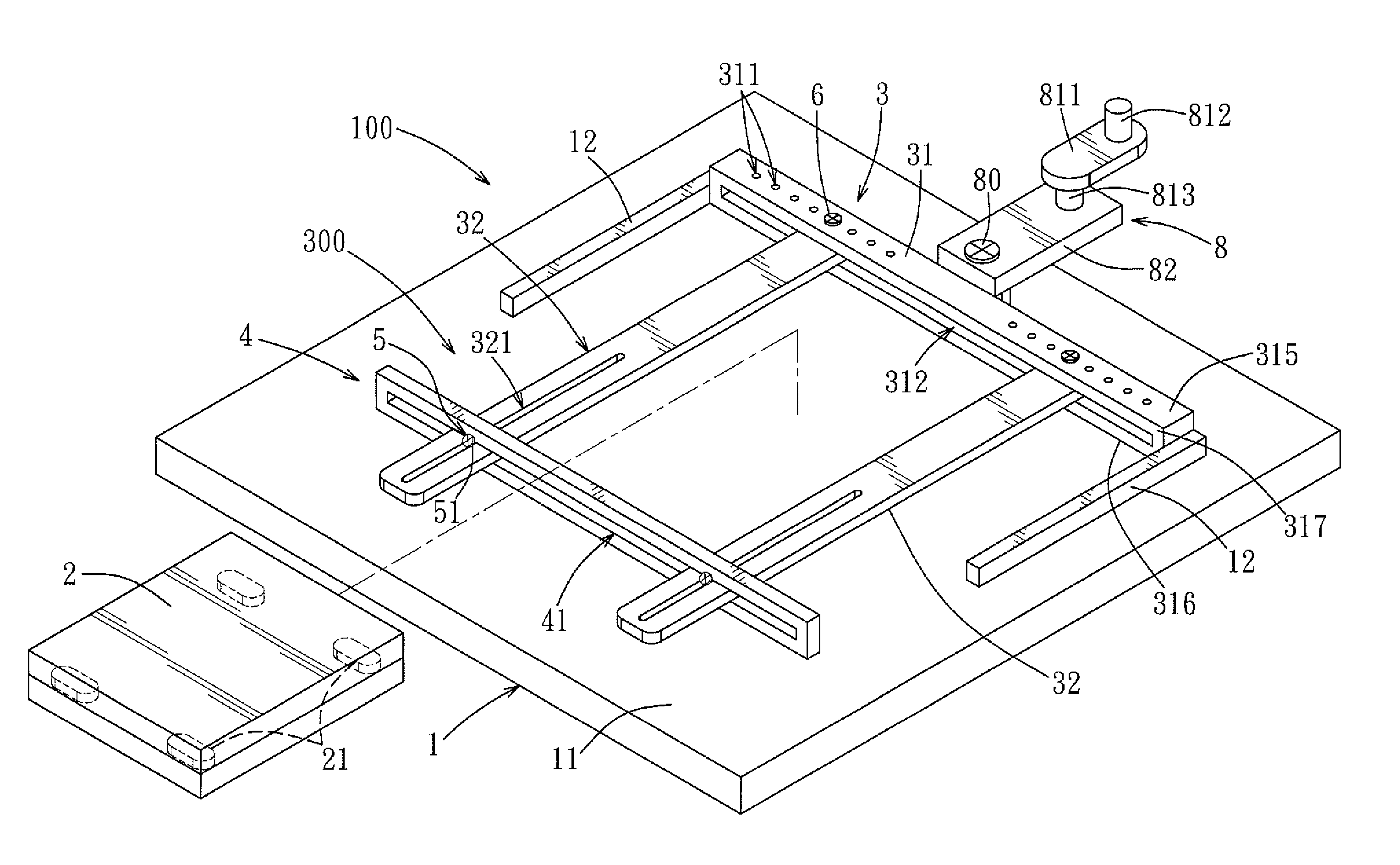
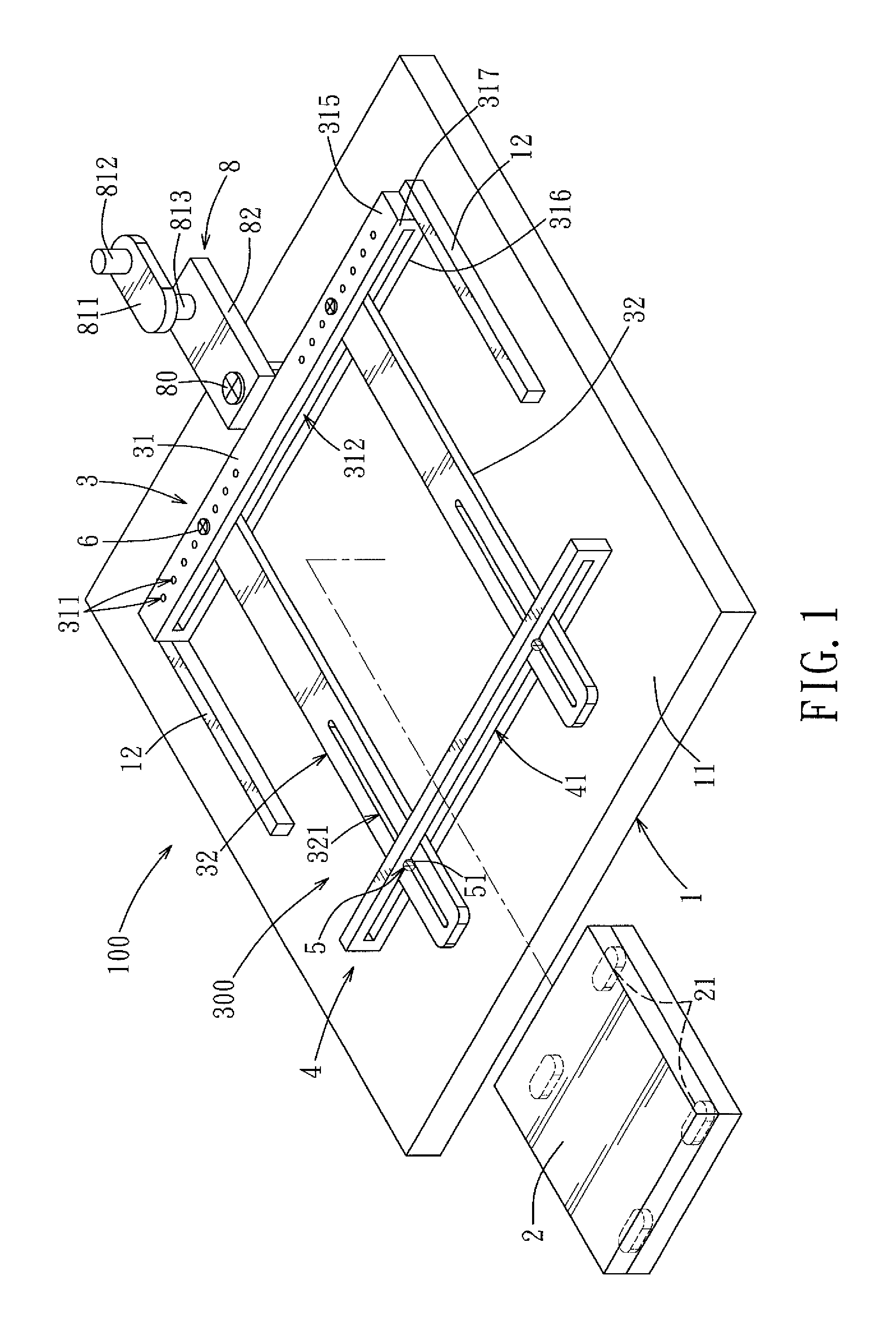
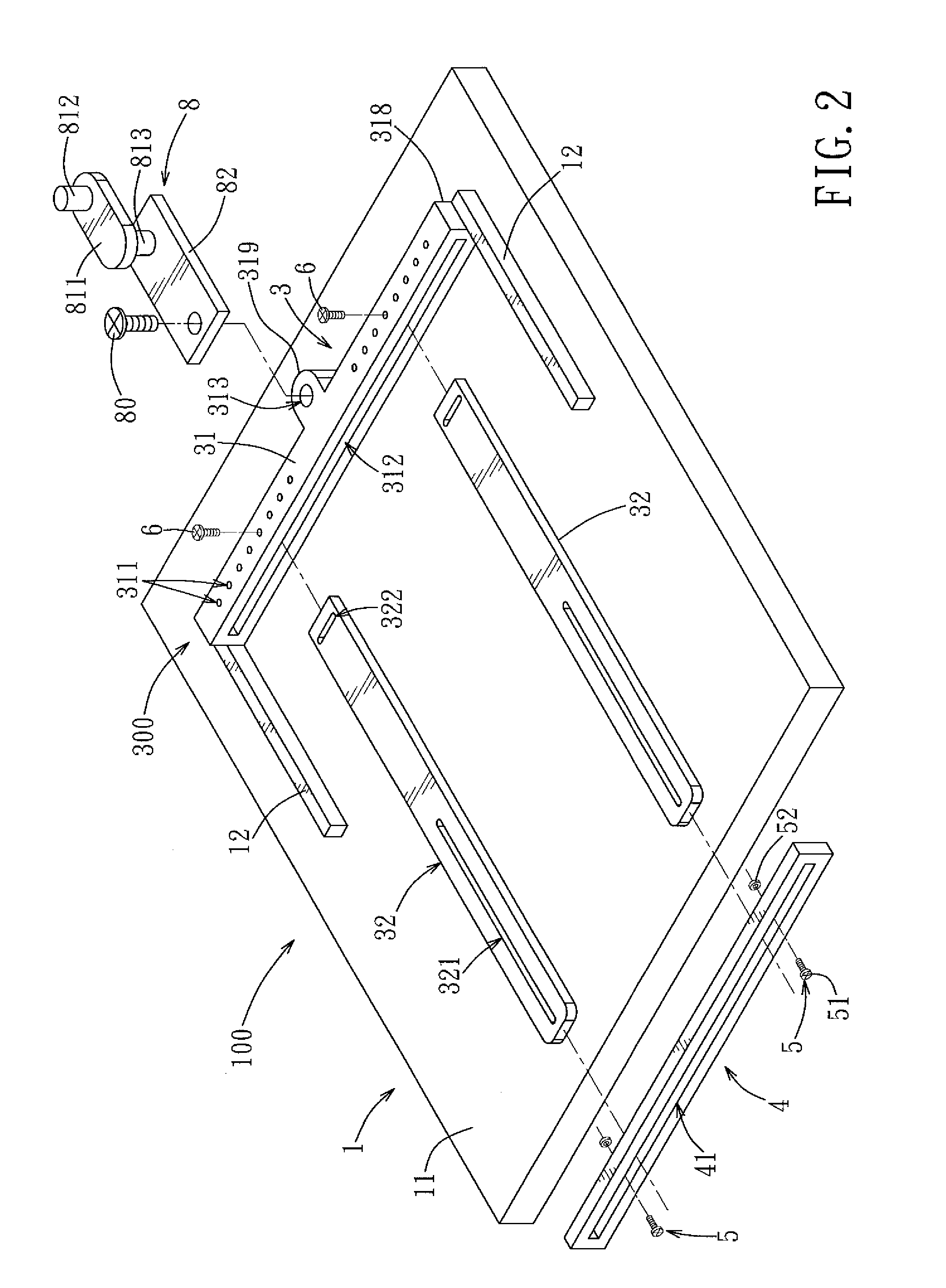
[0047]Referring to FIGS. 1 to 7, a friction testing device 100 according to the first embodiment of the present disclosure comprises a working platform 1, a clamping jig 300, and a push mechanism 8. Through these components, a friction test on a...


PUM

PropertyMeasurementUnit
distanceaaaaaaaaaa
heightaaaaaaaaaa
lengthaaaaaaaaaa

Abstract

A clamping jig for clamping a test object includes a first clamping member extending in a left-right direction, two second clamping members connected to and extending transversely of the first clamping member and spaced apart from each other in the left-right direction, and a third clamping member connected to and extending transversely of the second clamping members. The third clamping member is movable along the second clamping members in a front-rear direction to adjust a distance between the first and third clamping members. The first, second, and third clamping members are adapted to clamp therebetween the test object.

Description

CROSS-REFERENCE TO RELATED APPLICATION[0001]This application claims priority of Chinese Application No. 201110032674.6, filed on Jan. 30, 2011, the disclosure of which is incorporated herein by reference.BACKGROUND OF THE INVENTION[0002]1. Field of the Invention[0003]This disclosure relates to a clamping jig, and more particularly to a clamping jig for clamping a test object, a friction testing device having the clamping jig, and a friction test method.[0004]2. Description of the Related Art[0005]A friction testing device, as disclosed in Taiwanese Patent No. M357607, places a test object in a groove of a holding plate, after which a press plate is moved downward by an elevating mechanism so that a friction element and the test object are in contact with each other. Subsequently, a movable plate moves the holding plate and the test object reciprocally along a guide rail set, so that the test object is in frictional contact with and moves relative to the friction element. Through thi...

Claims


Application Information

Patent Timeline
Patent Type & Authority Applications(United States)
IPC IPC(8): G01N19/02B25B11/00
CPCG01N3/04G01N2203/0423G01N19/02
Inventor WANG, YI-CHIANGSHI, WEN-HUI
Owner WISTRON CORP
Why Eureka
Try Eureka