Eureka AIR delivers breakthrough ideas for toughest innovation challenges, trusted by R&D personnel around the world.

Subsurface safety valve including safe additive injection

Active Publication Date: 2012-08-02
WEATHERFORD TECH HLDG LLC
View PDF15 Cites 3 Cited by
  • Summary
  • Abstract
  • Description
  • Claims
  • Application Information

AI Technical Summary

Benefits of technology

[0032]In contrast, in the event of an incident, the production tube passing into its retracted position releases the safety plug which then occupies its closed position. This then prevents additive from flowing, and also prevents any unwanted rising of effluent from downhole to the surface via the line provided for the additive. Finally, when the production tube is back into its advanced position, this is accompanied by a corresponding movement of the safety plug, thereby once more releasing the additive passage.

Problems solved by technology

Such conditions lead to a drop in the hydraulic pressure in the control line, thereby causing a flap to close in such a manner as to block the upward stream of production fluids along the column.
This interrupts the application of hydraulic pressure against the actuator mechanism.
Nevertheless, such a method is not satisfactory insofar as it is particularly complex, since it involves removing the safety valve completely.
Nevertheless, that presents several drawbacks.
Furthermore, when injected into the control line, certain types of additive cannot control the valve in appropriate manner, particularly if they present a high degree of viscosity.
Nevertheless, that solution presents its own drawbacks.
Furthermore, in the event of a major malfunction, e.g. if the wellhead is absent, it is no longer possible for the operator to perform the above-mentioned injection under pressure, such that the effluent can rise along the injection line.
Such effluent leakage can lead to catastrophic phenomena of great magnitude, of the “oil spill” type if the effluent is oil.

Method used


Image

  • Subsurface safety valve including safe additive injection
  • Subsurface safety valve including safe additive injection
  • Subsurface safety valve including safe additive injection

Examples


Embodiment Construction

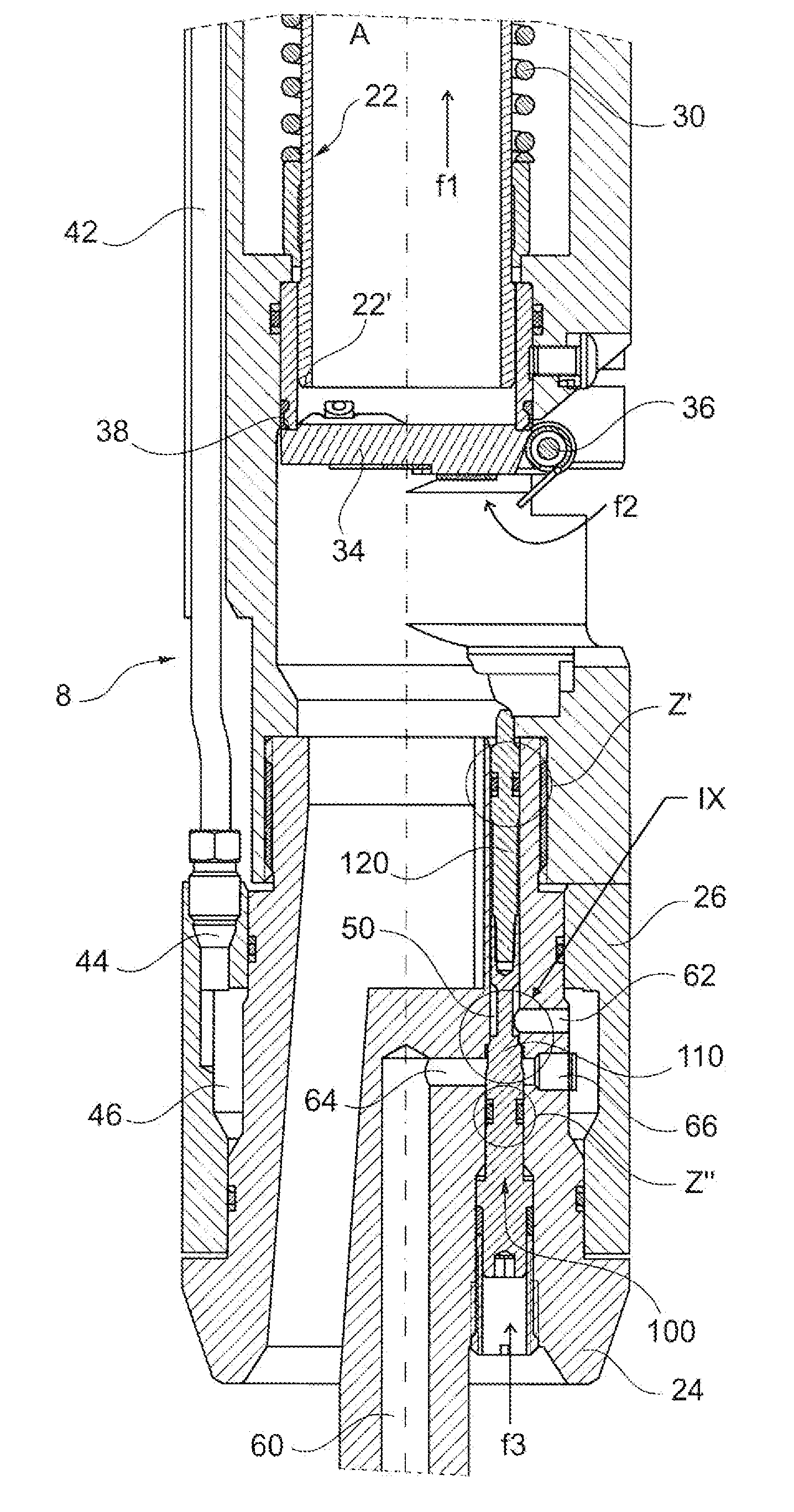
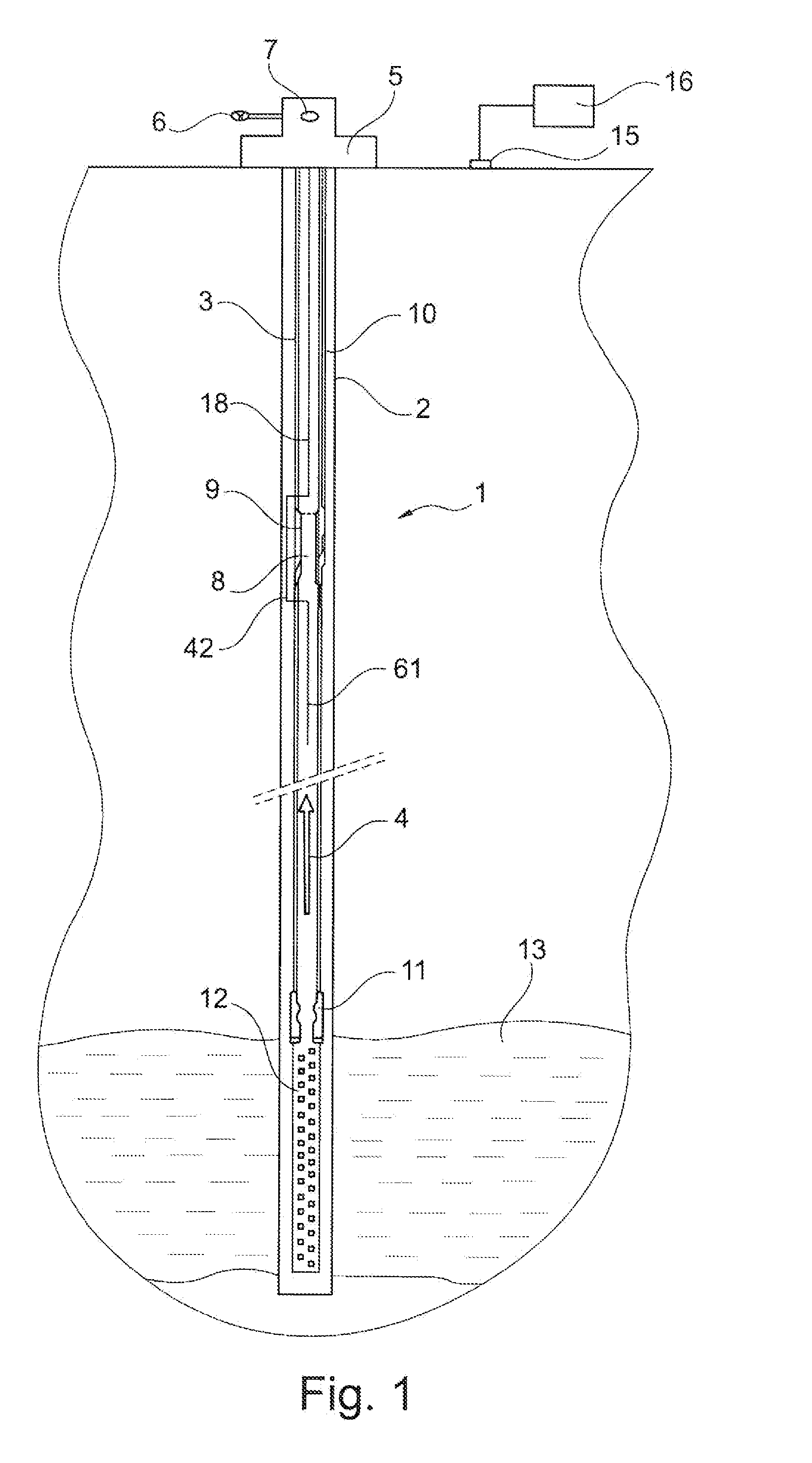
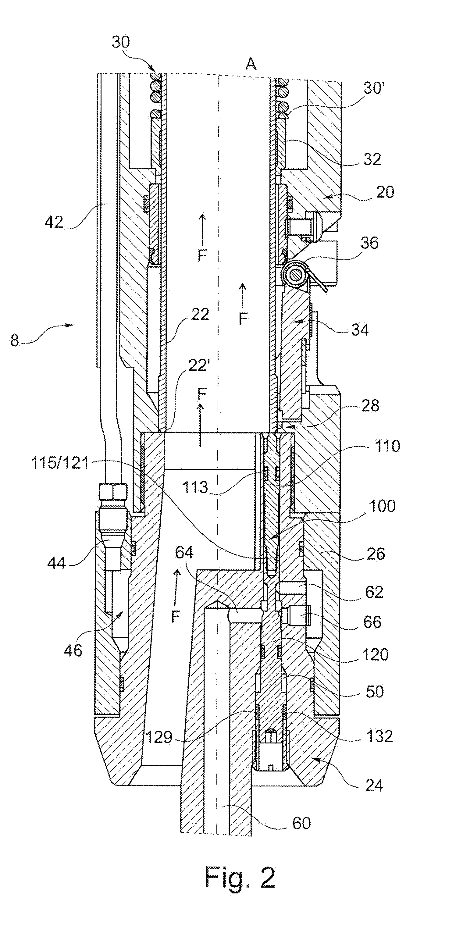
[0054]A detailed description is given below. Various terms that are used herein are defined below. When a term used in a claim is not defined below, it should be given the broadest definition that people skilled in the art give to the term, as shown in printed publications and published patents. In the description below, equivalent elements are referenced throughout the description and in the drawings by means of the same numerical references.

[0055]Although the drawings might be to scale, they need not necessarily be to scale, and the proportions of certain elements may be exaggerated in order to show characteristics and details of the invention more clearly. The person skilled in the art of subsurface safety valves will understand that the various embodiments of the invention may be used in all types of subsurface safety valve, including, but not limited thereto: injection valves that are accessible in the column and recoverable by cable; or valves controlled from the surface.

[0056...


PUM


Abstract

A safety valve for an effluent-production installation, the safety valve comprising a longitudinal shell in which there extends a production tube defining an inside volume for effluent flow, the tube being movable in translation inside the shell in an axial direction between an advanced position in which effluent flow is authorized from the bottom of the installation towards the surface, and a retracted position in which effluent flow is prevented, the valve being characterized in that it further includes a connection duct between a feed line for feeding at least one additive from the surface and an injection line for injecting the additive downhole, a safety plug being provided in the connection duct in order to close or open the duct depending on whether the production tube is in its retracted position or its advanced position.

Description

CROSS-REFERENCE TO RELATED APPLICATIONS[0001]This application claims benefit of French patent application serial number 1150632, filed Jan. 27, 2011, which is herein incorporated by reference in its entirety.BACKGROUND OF THE INVENTION[0002]1. Field of the Invention[0003]Embodiments of the invention relate to a surface-controlled subsurface safety valve (SCSSV) and also to an effluent-production installation including such a safety valve. In the meaning of the invention, the term “effluent” is used more particularly to designate oil or gas, but may also apply to other fluids, such as water.[0004]2. Description of the Related Art[0005]SCSSVs are commonly used for shutting-off oil or gas wells. Such SCSSVs are typically installed in a production column in a hydrocarbon production well, and they have the function of blocking the upward stream of fluid formation through the production column in the event of there being a problem or a dangerous condition occurring at the surface of the w...

Claims


Application Information

Patent Timeline
IPC IPC(8): E21B34/00
CPCE21B34/10E21B33/068Y10T137/87161Y10T137/87692
Inventor GARAY, SERGE
Owner WEATHERFORD TECH HLDG LLC
Why Eureka
Eureka Blog
Learn More