
Equipment module indicator handle and methods for indicating equipment module status

Active Publication Date: 2012-08-02
DELL PROD LP
View PDF4 Cites 23 Cited by
  • Summary
  • Abstract
  • Description
  • Claims
  • Application Information

AI Technical Summary

Benefits of technology

[0004]Disclosed herein are equipment module indicator handle apparatus and methods for displaying indications of the status of equipment module, such as a power supply module for a rack mounted information handling system like a server. In one embodiment, the disclosed apparatus and methods may be implemented by providing a light-conductive (e.g., transparent) handle body for a replaceable equipment module (e.g., such as a rack equipment module) combined with one or more light-emitting elements (e.g., light emitting diodes LEDs, miniature incandescent bulbs, etc.) disposed in light transmitting relation to the handle body (e.g., at least partially embedded within the handle body) and configured to function together with the handle body as an indicator of one or more status conditions for the equipment module. Advantageously, the disclosed equipment module handle may be implemented in one embodiment with little or no added unit cost over conventional solutions to provide a user with a more visible status indication that is removed from the rear wall of a rack mounted equipment module, while at the same time providing increased surface area for status indication without interfering with cooling air flow or other features of the module by combining (e.g., by embedding) light emitting element / s with a handle of the equipment module.
[0006]Advantageously, in one exemplary embodiment the disclosed apparatus and methods may be implemented in a manner that allows equipment module status to be displayed with increased visibility to a user, e.g., by providing a visual status indication at the surface of a handle body that is raised or outwardly displaced at a distance relative to an outer wall of an equipment module such as a rack equipment module. For example, a status indication (e.g., such as a fault condition) may be provided on the back or rear side of a equipment module such that it is clearly visible and more useable in a fully deployed condition (e.g., substantially not obscured by power cables, line cords, or other types of cables or connection equipment which are often present on the rear side of an equipment rack or other type of equipment module system) to service personnel. When used to display a fault condition of a server power supply, the disclosed apparatus and methods facilitate a user's quick and accurate determination of which power supply of a given rack mounted server should be replaced, thus reducing the possibility that a properly operating power supply is inadvertently pulled for replacement which can potentially result in an undesired server shut down.
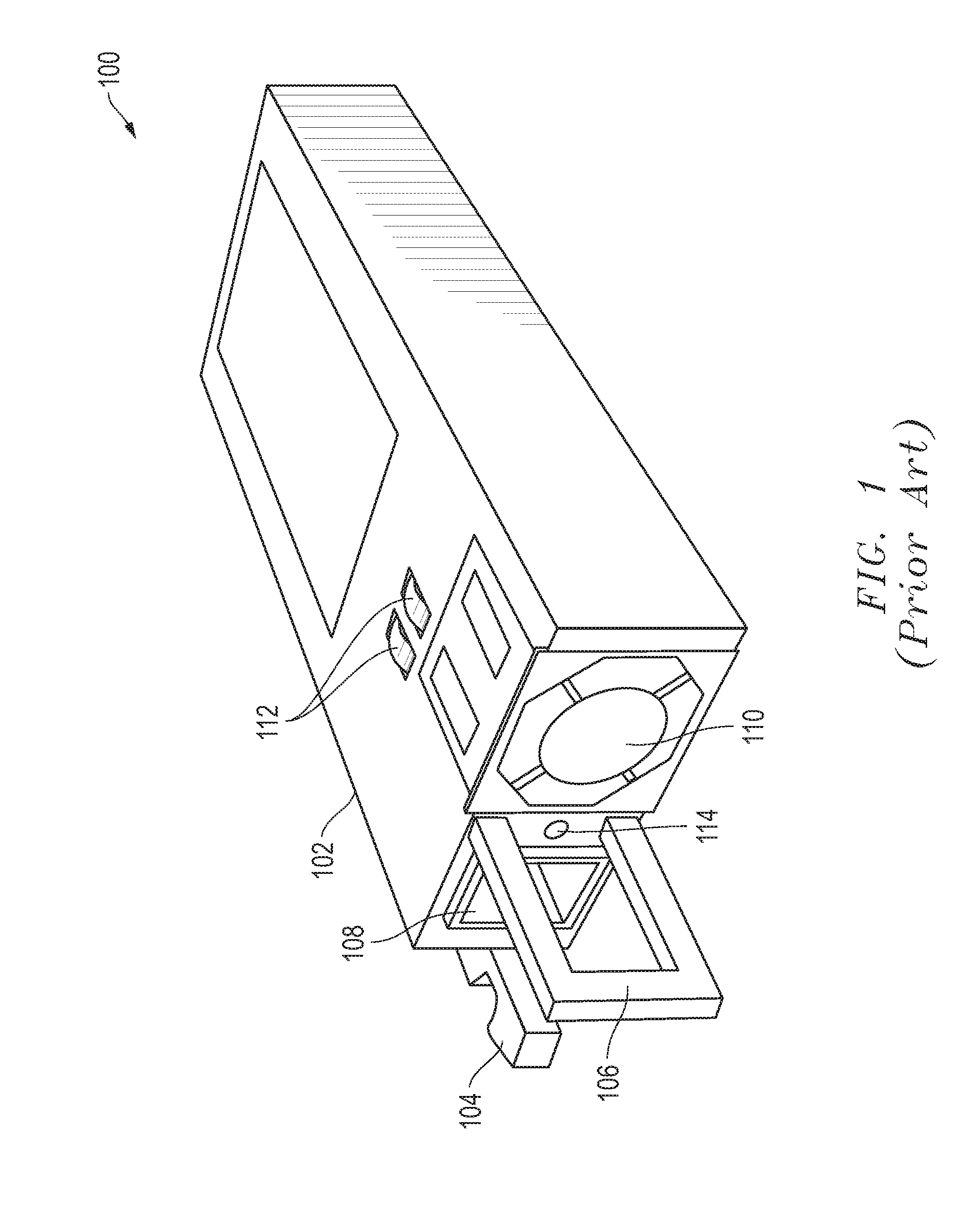
[0007]Furthermore, by integrating status display into a equipment module handle, the status display is not potentially obscured by the handle itself, as is often the case with conventional rack mounted equipment modules such as power supplies which employ a LED status indicator positioned beneath or behind the module handle. In this regard, the surface area of the rear wall of a conventional rack equipment power supply module is often limited due to the need for sharing space for power cord connector, cooling fan, status indicator and handle. The disclosed apparatus and methods may be thus implemented in one embodiment using a handle equipment indicator to display rack equipment status with increased visibility and without requiring additional chassis surface area. One or more icons may be optionally printed, molded, attached, or otherwise provided onto the handle surface itself such that no icons or associated artwork need be pad printed on the external surface of the chassis. This results in increased open area on the external chassis rear surface, thus improving thermal heat dissipation from the chassis during operation.

Problems solved by technology

When used to display a fault condition of a server power supply, the disclosed apparatus and methods facilitate a user's quick and accurate determination of which power supply of a given rack mounted server should be replaced, thus reducing the possibility that a properly operating power supply is inadvertently pulled for replacement which can potentially result in an undesired server shut down.
In this regard, the surface area of the rear wall of a conventional rack equipment power supply module is often limited due to the need for sharing space for power cord connector, cooling fan, status indicator and handle.

Method used


Image

  • Equipment module indicator handle and methods for indicating equipment module status
  • Equipment module indicator handle and methods for indicating equipment module status
  • Equipment module indicator handle and methods for indicating equipment module status

Examples


Embodiment Construction

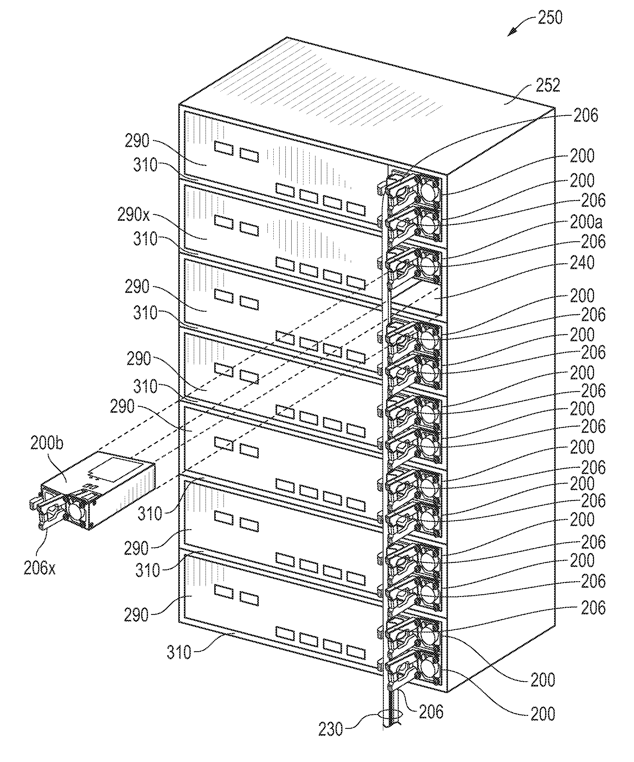
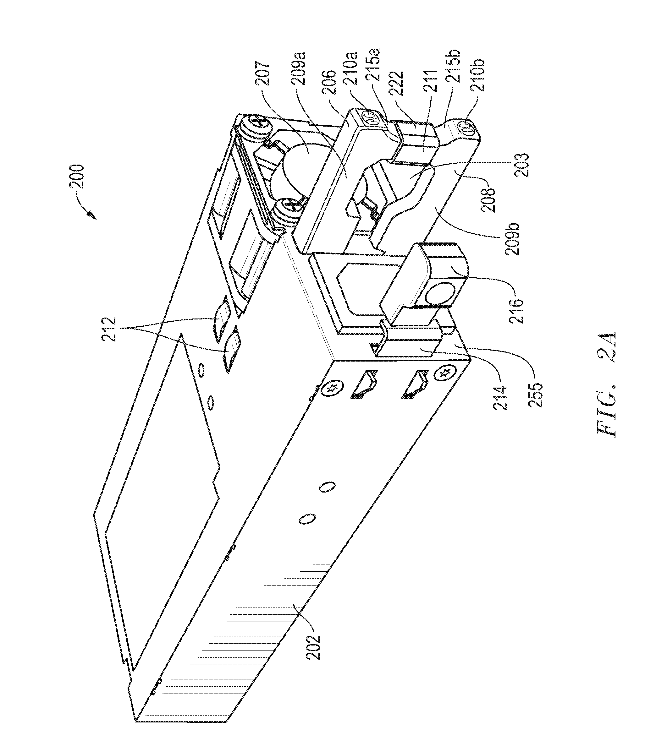
[0028]FIGS. 2A and 2B are different views illustrating an exemplary embodiment of a rack mounted equipment module provided in the form of a power supply module 200 for a rack mounted information handling system, such as a server. In this exemplary embodiment, power supply module 200 is configured as a hot-swappable power supply that may be slidably received into a complementary dimensioned power supply receptacle in a rack mounted server chassis. Although a hot-swappable power supply module 200 for a rack mounted information handling system is illustrated, it will be understood that the disclosed equipment module indicator handle apparatus and methods may be implemented with other types of equipment modules including, but not limited to, equipment modules including circuitry other than power supply circuitry (e.g., media drive modules, processing modules, etc.). Moreover, the disclosed equipment module indicator handle apparatus and methods may be implemented in other types of modul...


PUM


Abstract

Equipment module indicator handle apparatus and methods are provided for displaying indications of the status condition / s of equipment module circuitry using a light-conductive handle body that includes at least one handle leg at least partially composed of light conductive material and configured to transmit emitted light from a proximate end of the indicator handle toward a distal end of the indicator handle to visibly display a status condition of the module circuitry to a user on a surface of the indicator handle that is spaced apart from the wall of a chassis of the module.

Description

FIELD OF THE INVENTION[0001]This invention relates generally to equipment modules and, more particularly, to apparatus and methods for indicating status of equipment modules.BACKGROUND OF THE INVENTION[0002]As the value and use of information continues to increase, individuals and businesses seek additional ways to process and store information. One option available to users is information handling systems. An information handling system generally processes, compiles, stores, and / or communicates information or data for business, personal, or other purposes thereby allowing users to take advantage of the value of the information. Because technology and information handling needs and requirements vary between different users or applications, information handling systems may also vary regarding what information is handled, how the information is handled, how much information is processed, stored, or communicated, and how quickly and efficiently the information may be processed, stored,...

Claims


Application Information

Patent Timeline
IPC IPC(8): G08B5/00
CPCG06F1/188H05K7/1498H05K7/1487G06F1/26
Inventor CRISP, RICHARD A.WILLIAMS, DAVID W.
Owner DELL PROD LP
Learn More