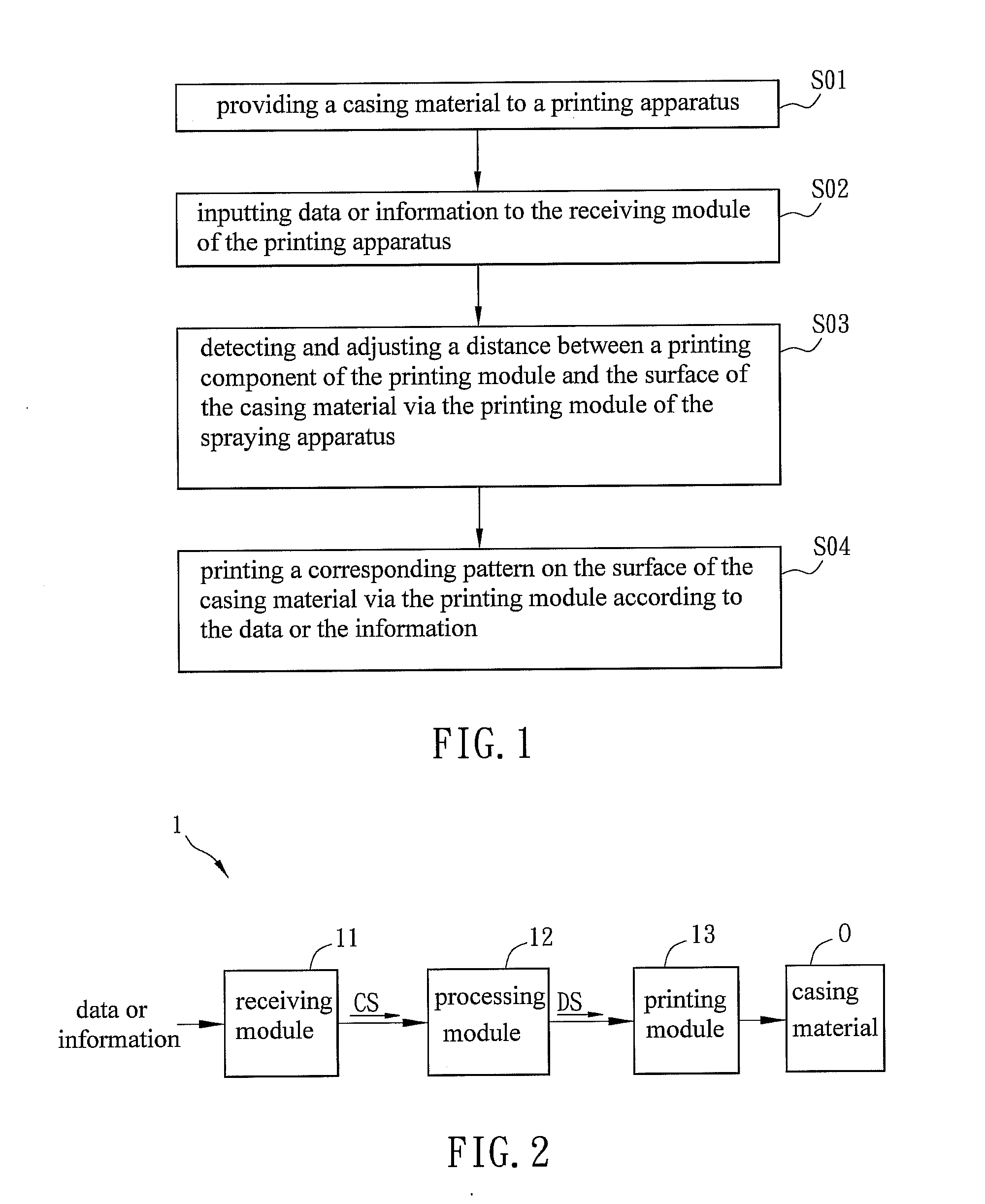
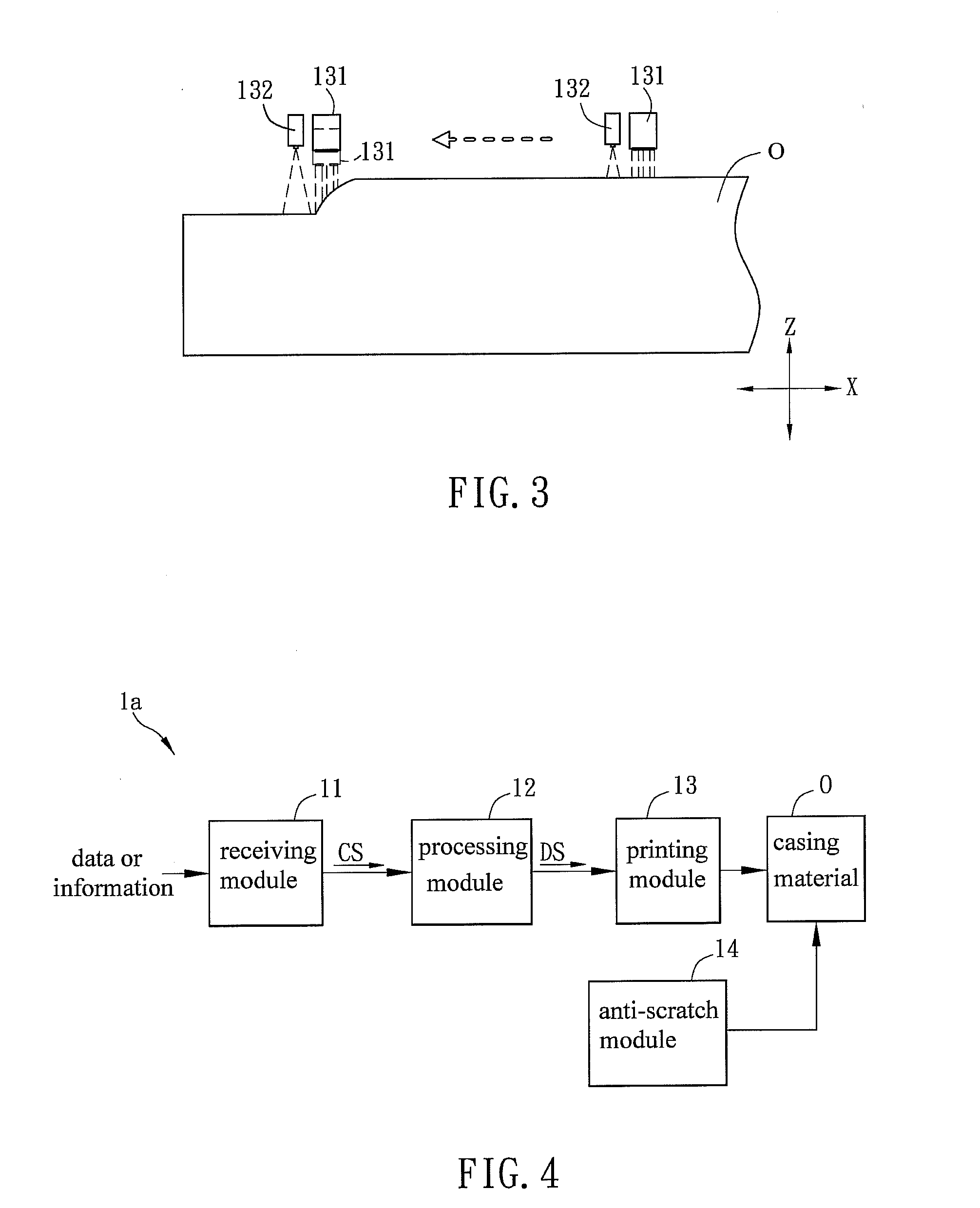
[0023]FIG. 1 is a flow chart showing steps of a casing printing method in a first embodiment, and FIG. 2 is a block diagram showing a printing apparatus in a first embodiment.
[0024]A printing apparatus 1 includes a receiving module 11, a processing module 12 and a printing module 13.
[0025]The casing printing method includes following steps: providing a casing material O to a printing apparatus 1 (S01); inputting data or information to the receiving module 11 of the printing apparatus 1 (S02); detecting and adjusting a distance between a printing component of the printing module 13 and the surface of the casing material O real-time via the printing module 13 of the printing apparatus 1 (S03); and printing a corresponding pattern on the surface of the casing material O via the printing module 13 according to the data or the information (S04). The casing material O may be plastic, glass, wood, ceramic, leather, metal, paper or textile, which is not limited herein.
[0026]The receiving module 11 outputs a control signal CS according to the data or the information. The receiving module 11 can receive the data or the information from other devices or apparatuses, and it can also receive the data or the information from a storage medium (such as a memory or an optical disk) which can be read by a computer. The data or the information includes pattern or color information of the casing material O to be processed. The pattern information may include multiple pattern styles, and the color may be black and white, or chromatic. After the processing module 12 receives the control signal CS outputted by the receiving module 11, the processing module 12 outputs a driving signal DS.
[0027]As shown in FIG. 3, the printing module 13 may further include a detecting component 132, a printing component 131 (such as a printing head) and a driving component (not shown). As shown in the right part of FIG. 3, if the surface of the casing material O is a plane surface, a surface with small curves, or a continuous plane, where the distance between the casing material O and the printing component 131 is almost constant. Moreover, as shown in the left part of FIG. 3, if the casing material O is a stereo model, a surface with a large curve, or a discontinuous plane, where the distance between the casing material O and the printing component 131 is not constant. The detecting component 132 can detect the distance changing between the printing component 131 and the casing material O, and the driving component adjusts according to the distance between the printing component 131 and the casing material O.
[0028]The printing module 13 sprays the corresponding pattern on the casing material O according to the driving signal DS outputted by the processing module 12. The printing module 13 sprays the pattern or color on the surface of the casing material O by printing. In printing patterns, the detecting component 132 detects the distance between the printing component 131 and the casing material O real-time, and the driving component moves the printing component 131 to an appropriate position to spray patterns. In detail, when the detecting component 132 detects the distance between the printing component 131 and the casing material O changes, the driving component controls the printing component 131 to move, so as to keep the distance between the printing component 131 and the casing material O constant and prevents the sprayed pattern distortion due to the appearance change of the casing material O. The driving component moves the printing component 131 along the direction Z to keep the distance between the printing component 131 and the casing material O constant. Thus, the printing apparatus 1 can spray a stereo model or the casing material O having a large curve or a discontinuous surface.
[0029]The printing module 13 may spray the pattern on the casing material O in a non-impact printing way. The ink jet printing can control the position of each ink droplet to make the ink injected to the surface of the casing material O directly by using the deflection of charged ink. Since the ink is injected, the printing module 13 does not need to contact with the casing material O, the printing method has a high speed, high data variability and can be applied to many types of materials. The printing module 13 may be a digital printing apparatus, such as an electronic printing apparatus or an inkjet printing apparatus, which is not limited herein.
[0030]As stated above, the casing printing method and the printing apparatus using the same can be applied to a casing of an electronic device, which is not limited herein.