Film-packaged electric device and its manufacturing method

a technology of electric devices and films, applied in the direction of cell components, final product manufacturing, sustainable manufacturing/processing, etc., can solve the problems of unconventional knowledge, unresolved problems, and depth of drawing, and avoid the effect of affecting the thermal sealing

Active Publication Date: 2006-09-21
NEC CORP
View PDF4 Cites 28 Cited by
  • Summary
  • Abstract
  • Description
  • Claims
  • Application Information

AI Technical Summary

Benefits of technology

[0019] As described above, according to the present invention, the close contact zone, which is a region in which the directly opposing casing films are not thermally sealed to each other but are in close contact with each other, is formed at a predetermined position and range of the casing films. From this fact, it is possible to relax a peeling force of the casing films acting on the root of the thermally sealed area, which tends to occur particularly when the electric device element is thick. As a result, a micro-crack can be prevented from occurring at the root of the thermally sealed area. Also, according to the method of manufacturing a film covered electric device of the present invention, the close contact zone can be extremely simply formed only by defining the distance between the thermal sealing head used to thermally seal the casing films and the electric device element, using a thermal sealing head generally used to thermally seal casing films.

Problems solved by technology

However, as the cell element has a larger thickness, other problems, which have not been conventionally known, will occur.
However, since there are limitations to the depth of drawing when a casing material made of a film is formed with a cup area, it is often necessary to form not only a casing material on one side but casing materials on both sides with cup areas, and place the cup areas opposite to each other to place therein a cell element, the thickness of which is twice the depth of drawing.
The problem is that if a thermally sealed area of the casing materials is too close to the cell element, the root of the thermally sealed area is pressed against the cell element by the action of the atmospheric pressure on the casing materials when the film covered battery is sealed in a reduced pressure atmosphere and returned back into the atmospheric pressure.
When the root of the thermally sealed area is pressed against the cell element, an unwanted stress is immanent at the root of the thermally sealed area.
This stress causes the occurrence of a micro-crack into the casing materials.
Also, this problem is prominent when the cup areas are formed in the casing materials on both sides of the cell element, and the cup areas are placed opposite to each other for sealing the cell element therein.

Method used


Image

  • Film-packaged electric device and its manufacturing method
  • Film-packaged electric device and its manufacturing method
  • Film-packaged electric device and its manufacturing method

Examples


example 1

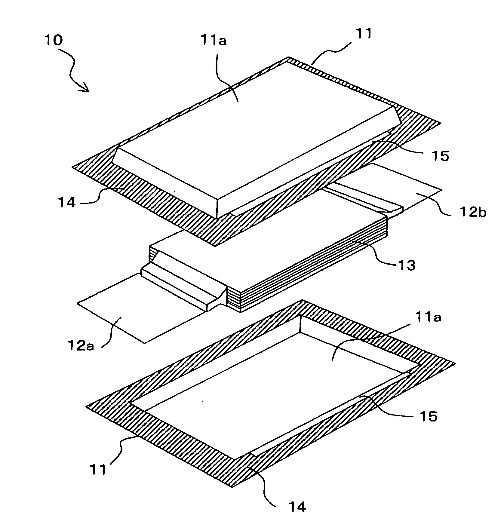
[0064] A plurality of positive poles and a plurality of negative poles, made by coating an electrode material on both surfaces of metal foils, were alternately stacked through separators. An aluminum foil was used for the metal foil for the positive poles. A copper foil was used for the metal foil for the negative poles. A micro-porous film made of polyethylene of 30 μm thick was used as the separators. The separators, which are rectangular, was made to have a size of 75 mm wide and 130 mm deep, which was larger than the size of the positive pole by 2 mm both in length and width, and was substantially the same size as the positive pole. The outermost pole was chosen to be the negative pole, and the separator was disposed outside this negative pole as well. Specifically, the order is separator / negative pole / separator / positive pole / separator / . . . / negative pole / separator. The thickness of the laminate made up of the positive poles, negative poles, and separators was chosen to be 10 ...

example 2

[0072] A film covered battery was fabricated in a similar manner to Example 1 except that a cell element was spaced apart by 3 mm from the thermal sealing head when two longer sides were thermally sealed.

[0073] In this example, a close contact zone was also formed between a thermally sealed area of the two longer sides and the cell element in the fabricated film covered battery, as is the case with Example 1. The width of the close contact zone ranged from 1.5 to 2.5 mm. Also, the two longer sides curved in a similar manner to Example 1, where a central portion, having the largest amount of curving, indented by approximately 1 mm inwardly from both ends, and a close contact zone was also formed in width of approximately 1.5 mm in the central portion.

[0074] When the film covered battery was disassembled to observe the thermally sealed area of the longer sides, a flash of resin was found approximately 0.5 mm at the root of the thermally sealed area in this example, as is the case wi...


PUM

PropertyMeasurementUnit
widthaaaaaaaaaa
thicknessaaaaaaaaaa
thicknessaaaaaaaaaa

Abstract

The occurrence of micro-crack is prevented at the root of a thermally sealed area of casing materials even if a thick electric device element is sealed.
Film covered battery 10 has cell element 13 to which leads 12a, 12b are connected, and casing films 11 for sealing cell element 13 with leads 12a, 12b extended therefrom. Casing films 11 are thermally sealed along the periphery to seal cell element 13. Thermally sealed area 13 of casing films 11 is positioned between both surfaces of cell element 13 in the thickness direction of cell element 13. On a side of casing films 11 from which leads 12a, 12b are not extended, close contact zone 15, in which casing films 11 are not thermally sealed to each other but are in close contact with each other, is formed continuously to a space which receives cell element 13. Close contact zone 15 has a length of one-half or more of the distance from one end to the other end of an inner edge of thermally sealed area 14.

Description

TECHNICAL FIELD [0001] The present invention relates to a film covered electric device which has an electric device element such as a chemical cell element or a capacitor element contained in a casing material made of a film. BACKGROUND ART [0002] Conventionally, as a film covered battery which uses a thermally sealable film as a casing material, there is known one which has a structure in which a cell element is covered with a laminate film, and open edges of the laminate film are thermally sealed, with lead ends of a positive pole and a negative pole connected to the cell element protruded from the laminate film, thereby hermetically sealing (hereinafter simply called “seal” in some cases) the cell element. The laminate film used herein is made up of a metal layer and a thermally sealable resin layer laminated to each other. This type of film covered battery has the advantage of being readily reduced in thickness, and most of conventional film covered batteries have flat shapes. [...

Claims


Application Information

Patent Timeline
Patent Type & Authority Applications(United States)
IPC IPC(8): H01M2/08H01M10/04H01G2/10H01G9/00H01G9/08H01M10/0525H01M10/058H01M10/36H01M50/105H01M50/178H01M50/548H01M50/557
CPCH01G2/10H01G9/08H01M2/0207H01M2/021H01M2/0212Y10T29/4911H01M2/0404H01M10/0525H01M10/058Y10T29/49112H01M2/0287Y02E60/10H01M50/557H01M50/124Y02P70/50H01M50/105H01M50/178H01M50/548H01G9/00H01M10/0585
Inventor YAGETA, HIROSHIOTOHATA, MAKIHIRO
Owner NEC CORP
Why Eureka
Try Eureka