Reflective and transparent liquid crystal display device

a liquid crystal display and transparent technology, applied in the field of reflection and transparent liquid crystal display, can solve the problems of large amount of power consumption, reduced aperture ratio, spatial and temporal limitations of reflective liquid crystal display, etc., and achieve the effect of reducing or effectively preventing a time difference, and further improving reflectivity and transmittan

Inactive Publication Date: 2012-08-02
PUSAN NAT UNIV IND UNIV COOPERATION FOUND +1
View PDF7 Cites 20 Cited by
  • Summary
  • Abstract
  • Description
  • Claims
  • Application Information

AI Technical Summary

Benefits of technology

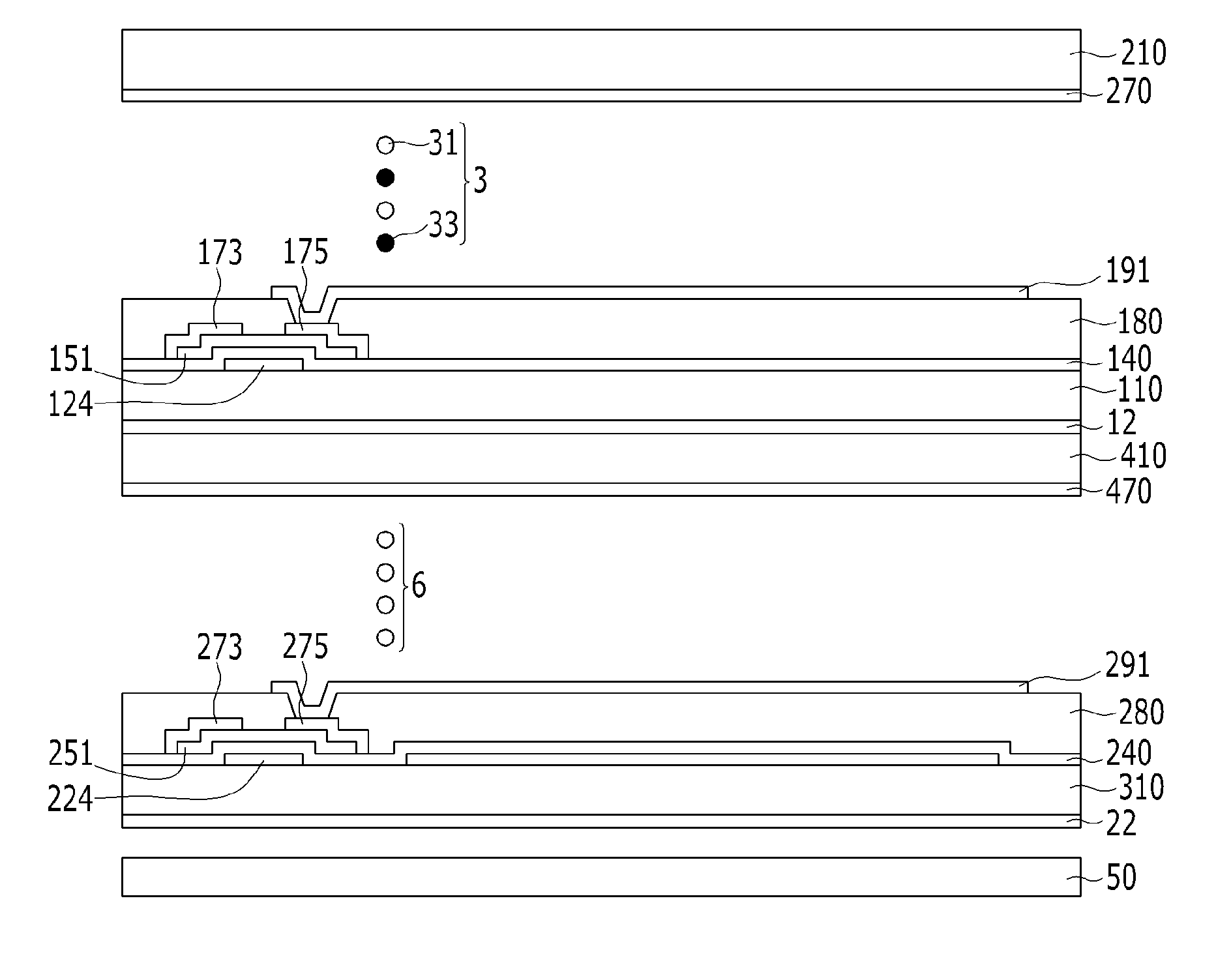
[0041]Exemplary embodiments of the transflective liquid crystal display according to the invention can realize a reflection mode and a transmission mode with one liquid crystal panel so that reflectivity and transmittance can be further improved compared to a conventional liquid crystal display that realizes a reflection mode and a transmission mode with two liquid crystal panels, and can reduce or effectively prevent a time difference from occurring when external light passes through two liquid crystal lay

Problems solved by technology

The use of the backlight is essential in a backlit liquid crystal display, but the backlight consumes a large amount of power so that the transmissive liquid crystal display is inappropriate to be used as a display of a portable device.
However, the reflective liquid crystal display has spatial and temporal limitations because the optical effect of the reflective liquid crystal depends on the peripheral environment.
However, a technique for realizing a complex mode in a single cell gap and a technique for applying a dual cell gap to a single mode have complex process problems and one pixel is divided into a transmission area and a reflection area so that the ape

Method used


Image

  • Reflective and transparent liquid crystal display device
  • Reflective and transparent liquid crystal display device
  • Reflective and transparent liquid crystal display device

Examples


Embodiment Construction

[0061]The invention will be described more fully hereinafter with reference to the accompanying drawings, in which exemplary embodiments of the invention are shown. As those skilled in the art would realize, the described embodiments may be modified in various different ways, all without departing from the spirit or scope of the invention.

[0062]In the drawings, the thickness of layers, films, panels, regions, etc., are exaggerated for clarity. Like reference numerals designate like elements throughout the specification. It will be understood that when an element such as a layer, film, region, or substrate is referred to as being “on” another element, it can be directly on the other element or intervening elements may also be present. In contrast, when an element is referred to as being “directly on” another element, there are no intervening elements present.

[0063]It will be understood that, although the terms first, second, third, etc., may be used herein to describe various element...


PUM


Abstract

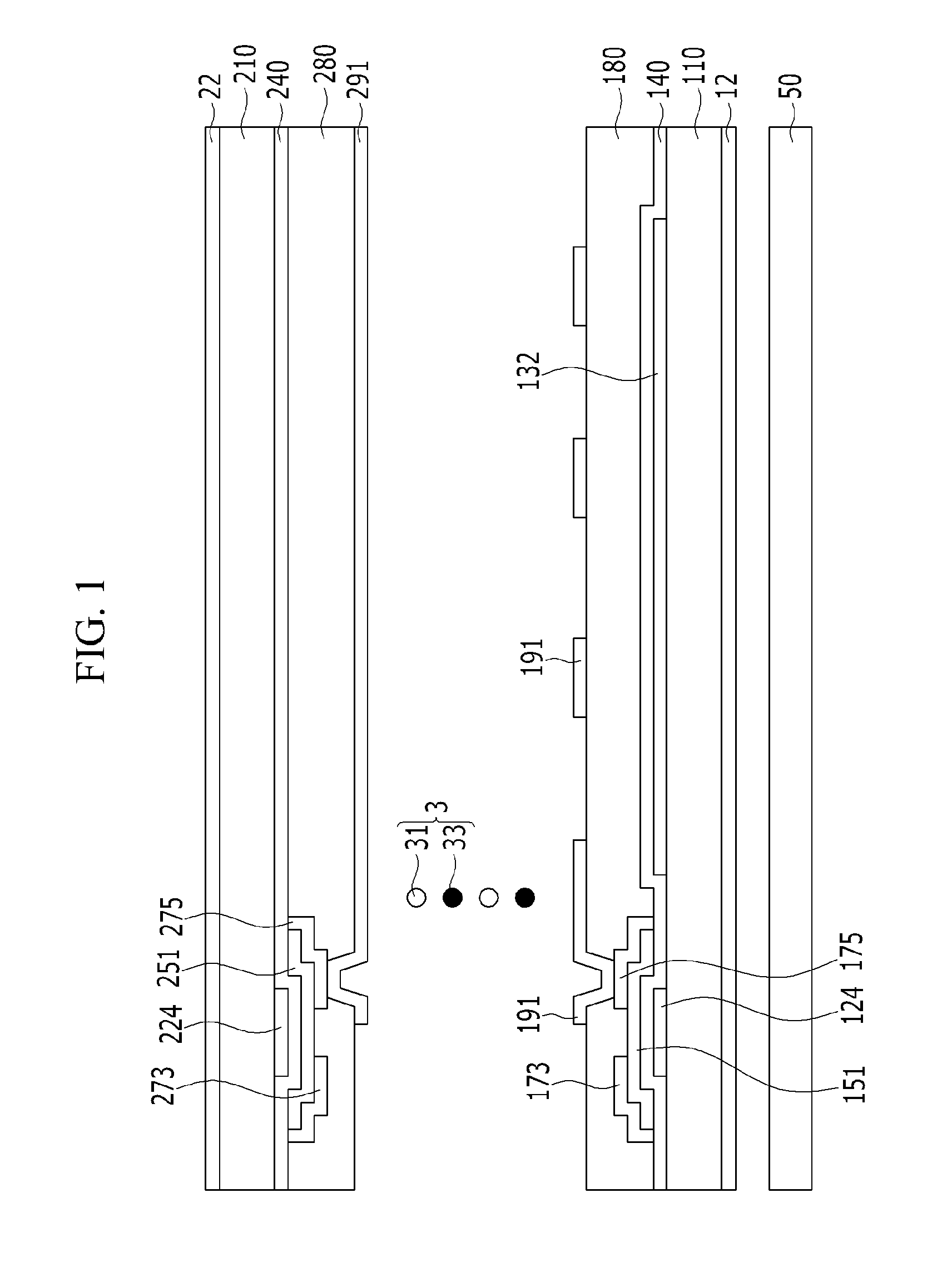
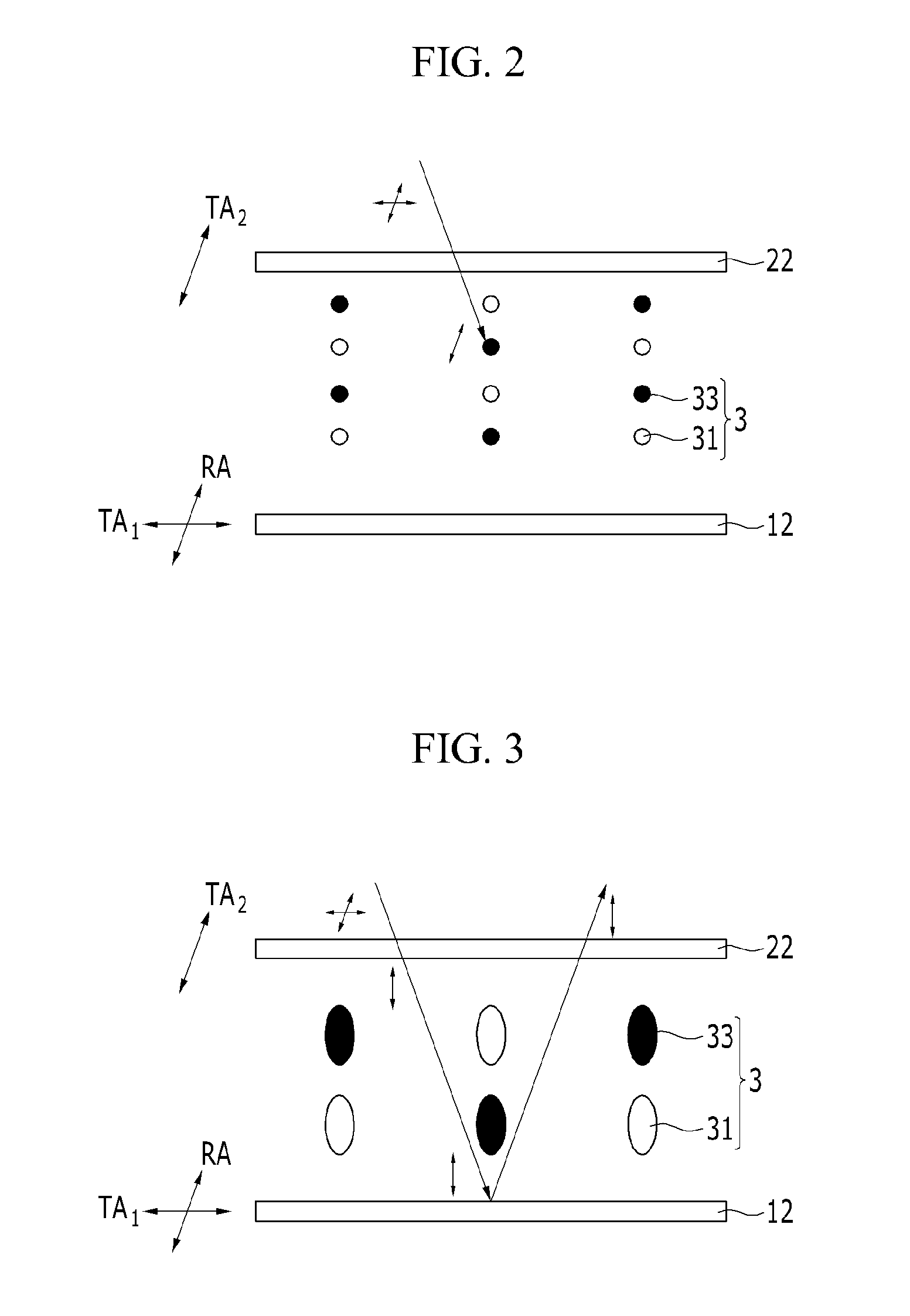
A transflective liquid crystal display includes a liquid crystal panel including a first substrate, a second substrate, a liquid crystal layer, the first and second substrates arranged to face each other and the liquid crystal layer between the first and second substrates, a reflection polarizer and an absorption polarizer at opposing outer sides of the liquid crystal panel, and a backlight unit at an outer side of the liquid crystal panel and supplying light to the inside of the liquid crystal panel. A reflective axis of the reflection polarizer is parallel with a transmissive axis of the absorption polarizer, the transmissive axis of the reflection polarizer perpendicularly crosses the transmissive axis of the absorption polarize, and the liquid crystal layer includes liquid crystal molecules and a dichroic dye.

Description

[0001]This application claims priority to Korean Patent Application No. 10-2011-0010214 filed on Feb. 1, 2011, and all the benefits accruing therefrom under 35 U.S.C. §119, the entire contents of which are incorporated herein by reference.BACKGROUND OF THE INVENTION[0002](a) Field of the Invention[0003]The invention relates to a transflective liquid crystal display. More particularly, the invention relates to a transflective liquid crystal display that can improve reflectivity and transmittance, and prevent gray inversion in reflective and transmission modes during occurrence of a time difference in generation of external light.[0004](b) Description of the Related Art[0005]A liquid crystal display as one of flat panel display devices that are widely used includes two display panels where field generating electrodes such as a pixel electrode and a common electrode are formed, and a liquid crystal layer interposed therebetween, and the liquid crystal display generates an electric fiel...

Claims


Application Information

Patent Timeline
IPC IPC(8): G02F1/1335
CPCG02F1/133536G02F1/133555G02F2203/30G02F1/13475G02F1/13624G02F2203/62G02F2001/133368G02F2001/133638G02F2001/134372G02F2201/121G02F2202/043G02F1/13737G02F1/133368G02F1/133638G02F1/134372G02B5/003G02B6/0055G02F1/1335G02F1/1343G02F1/133G02F1/1347
Inventor CHEONG, BYOUNG-HOYOU, JAE-HORHO, SOON-JOONKIM, JAE-CHANGYOON, TAE-HOONKIM, KI-HANJIN, HYE-JUNG
Owner PUSAN NAT UNIV IND UNIV COOPERATION FOUND
Why Eureka
Try Eureka