
System and method for multi-sectional truss spar hull for offshore floating structure

a technology of multi-sectional truss spars and offshore floating structures, which is applied in the direction of special-purpose vessels, vessel construction, transportation and packaging, etc., can solve the problems of large-scale fabrication of large-scale components, cost and complexity of the process, and the limited size of some such platforms

Inactive Publication Date: 2012-08-02
TECH FRANCE SA
View PDF2 Cites 12 Cited by
  • Summary
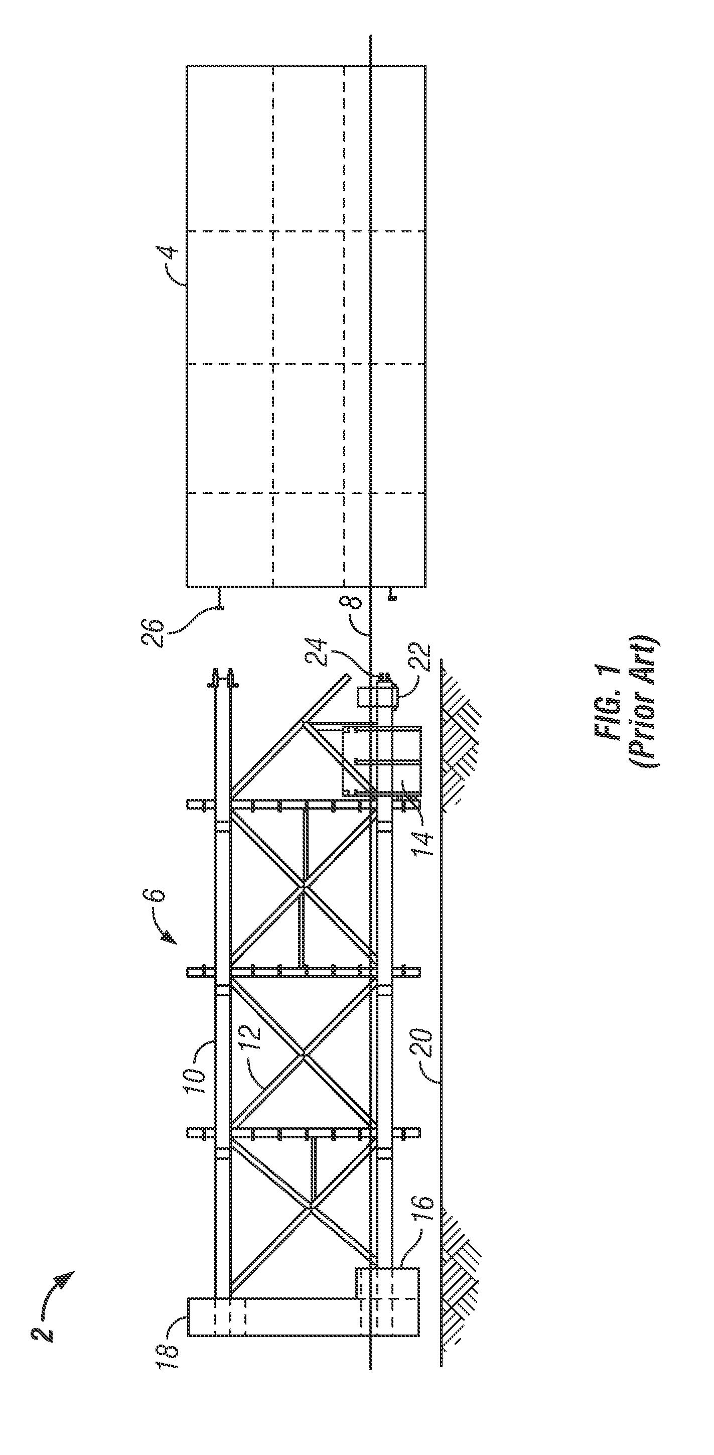
  • Abstract
  • Description
  • Claims
  • Application Information

AI Technical Summary

Benefits of technology

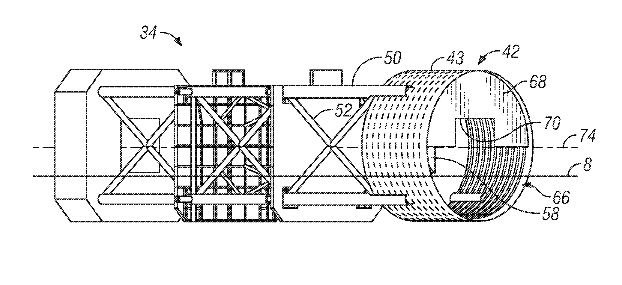
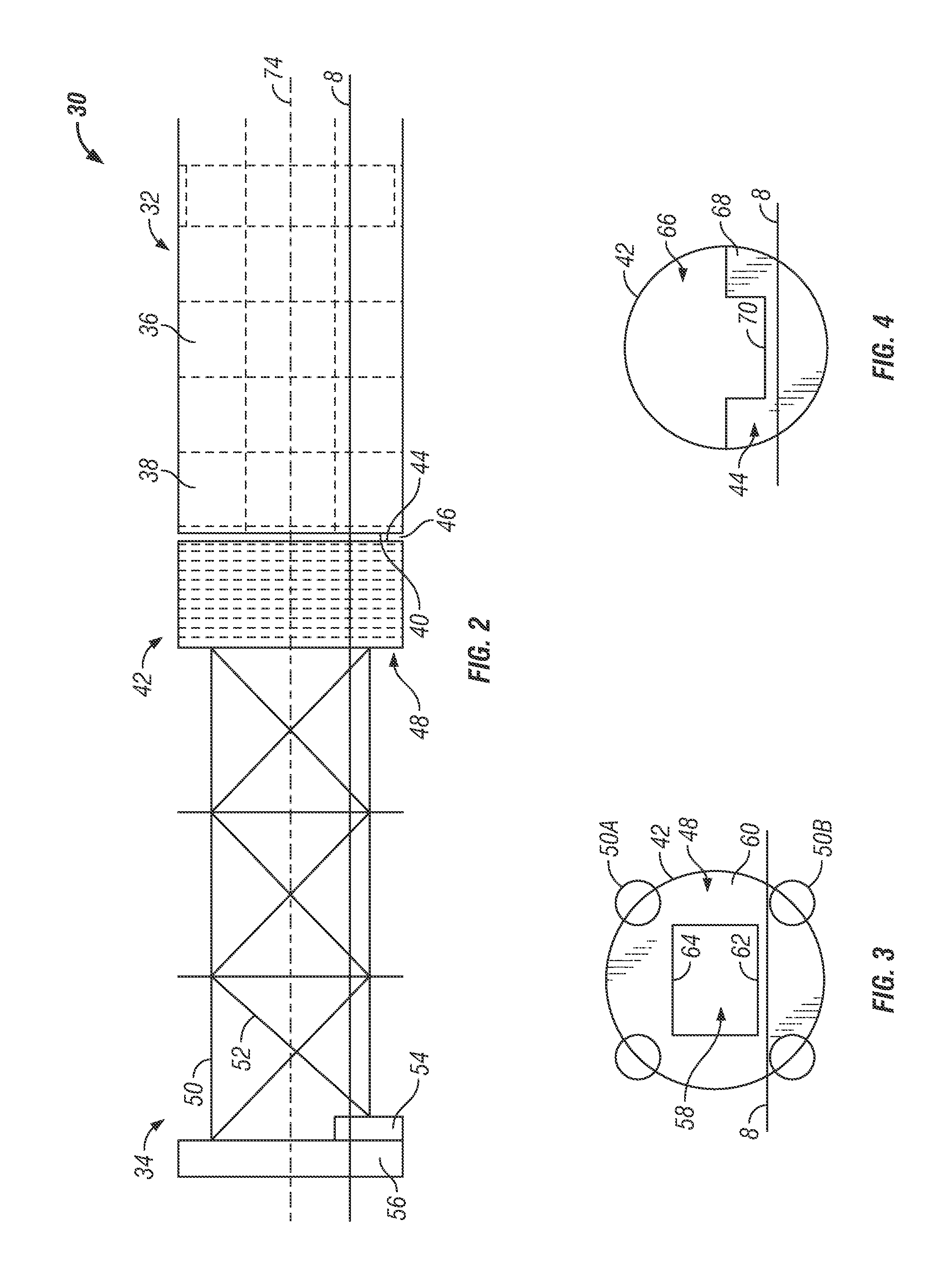
[0012]The present disclosure provides an improved design for a multi-sectional truss spar hull platform having a truss and a spar hull. One or more sections can be transported to a designated location and off-loaded into water from an available transport vessel. The truss includes a skirt tank at the upper end of truss that can be coupled to the lower end of the hull. The skirt tank can provide buoyancy during float-off and mating operations to the hull. The skirt tank is designed to allow the portion above the water to be coupled to the hull in a first orientation, the truss with the skirt tank rotated with the hull in the water to a second orientation to expose the previously underwater portion, and then the previously underwater portion can be coupled together above the water. The integral skirt tank will be flooded after the spar hull is up-ended.

Problems solved by technology

The size of some such platforms has traditionally been limited by the capacity of vessels to haul the platform.
Thus, while the fabrication process showed that the truss and hull could be made separately and assembled while floating to complete fabrication of such a large offshore structure, the process was costly and intricate.
The fabrication was considerably challenging to align the large components and maintain alignment and dimensional control during the welding and in underwater conditions using the cofferdams.

Method used


Image

  • System and method for multi-sectional truss spar hull for offshore floating structure
  • System and method for multi-sectional truss spar hull for offshore floating structure
  • System and method for multi-sectional truss spar hull for offshore floating structure

Examples


Embodiment Construction

[0025]The Figures described above and the written description of specific structures and functions below are not presented to limit the scope of what Applicant has invented or the scope of the appended claims. Rather, the Figures and written description are provided to teach any person skilled in the art to make and use the inventions for which patent protection is sought. Those skilled in the art will appreciate that not all features of a commercial embodiment of the inventions are described or shown for the sake of clarity and understanding. Persons of skill in this art will also appreciate that the development of an actual commercial embodiment incorporating aspects of the present disclosure will require numerous implementation-specific decisions to achieve the developer's ultimate goal for the commercial embodiment. Such implementation-specific decisions may include, and likely are not limited to, compliance with system-related, business-related, government-related, and other co...


PUM


Abstract

The present disclosure provides an improved design for a multi-sectional truss spar hull platform having a truss and a spar hull. One or more sections can be transported to a designated location and off-loaded into water from an available transport vessel. The truss includes a skirt tank at the upper end of truss that can be coupled to the lower end of the hull. The skirt tank can provide buoyancy during float-off and mating operations to the hull. The skirt tank is designed to allow the portion above the water to be coupled to the hull in a first orientation, the truss with the skirt tank rotated with the hull in the water to a second orientation to expose the previously underwater portion, and then the previously underwater portion can be coupled together above the water. The integral skirt tank will be flooded after the spar hull is up-ended.

Description

CROSS REFERENCE TO RELATED APPLICATIONS[0001]Not applicable.STATEMENT REGARDING FEDERALLY SPONSORED RESEARCH OR DEVELOPMENT[0002]Not applicable.REFERENCE TO APPENDIX[0003]Not applicable.BACKGROUND OF THE INVENTION[0004]1. Field of the Invention[0005]The disclosure generally relates to offshore floating structures. More particularly, the disclosure relates to large, multi-sectional, offshore floating structures that are fabricated and then assembled while floating in water.[0006]2. Description of the Related Art[0007]A spar platform is a type of floating offshore structure typically used in very deep waters and is among the largest offshore platforms in use. A spar platform includes a large cylinder or hull supporting a typical rig topsides. The hull does not extend all the way to the seafloor and typically rely on a traditional mooring system to maintain their position. The spar platform can further include a truss structure of a generally open construction that is disposed below th...

Claims


Application Information

Patent Timeline
Patent Type & Authority Applications(United States)
IPC IPC(8): B63B38/00
CPCB63B9/065B63B2035/442B63B2009/067B63B75/00B63B77/00
Inventor LUO, MICHAEL Y.H.ZHOU, ZHENGQUANGEBARA, JOSEPH M.
Owner TECH FRANCE SA
Learn More