Work Vehicle

a technology for working vehicles and cranes, applied in cranes, lifting devices, constructions, etc., can solve problems such as confusion of operators, and achieve the effect of preventing high-speed operations

Active Publication Date: 2012-08-02
YANMAR POWER TECHNOLOGY CO LTD
View PDF12 Cites 6 Cited by
  • Summary
  • Abstract
  • Description
  • Claims
  • Application Information

AI Technical Summary

Benefits of technology

[0007]The present invention has been accomplished under such circumstances, and an object of the present invention is to provide a work vehicle capable of perfor

Problems solved by technology

However, in this structure, in a case where an implement (such as the roll grab) including an oil hydraulic cylinder is attached,

Method used


Image

  • Work Vehicle
  • Work Vehicle
  • Work Vehicle

Examples


Embodiment Construction

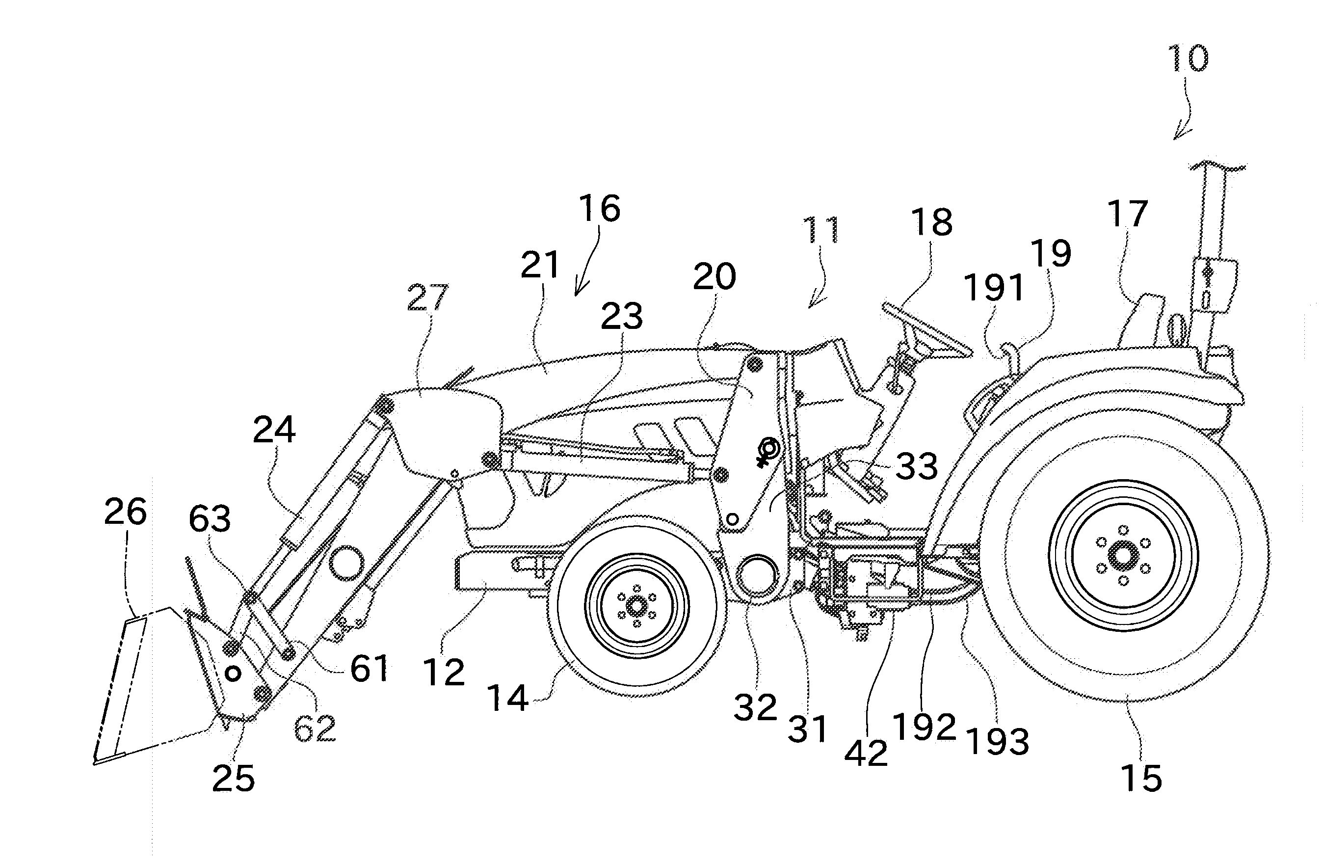
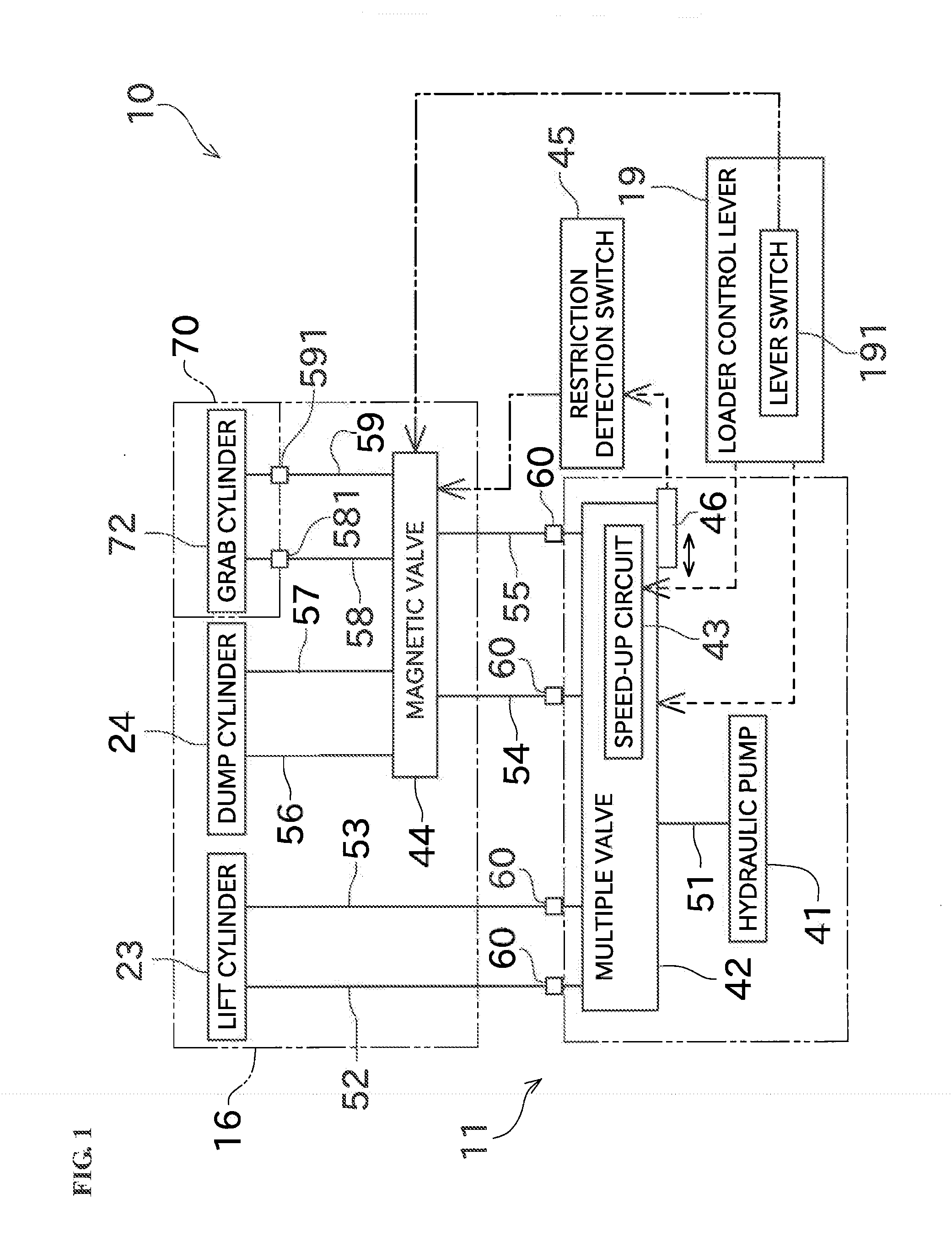
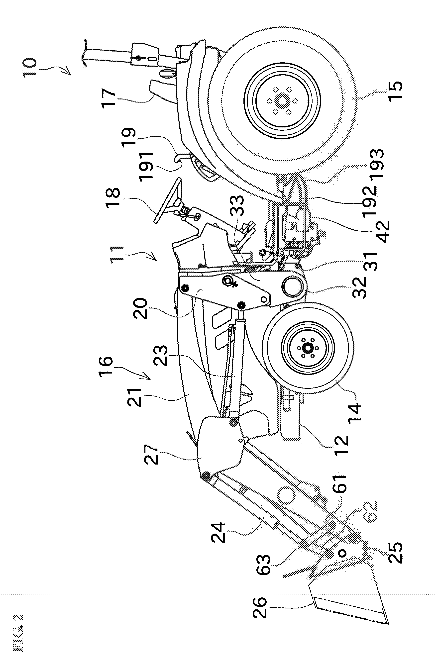
[0027]Hereinafter, a preferred embodiment of the present invention will be described with reference to the accompanying drawings FIG. 2 is a perspective view showing an entire structure of a tractor 10 according to an embodiment of the present invention. FIG. 3 is a perspective view showing structure around a loader control lever 19, a multiple valve 42, and a magnetic valve 44, FIG. 4 is a side view showing a right boom 21 as seen from the vehicle body side. In the present specification, by the simple expression of “left side” and “right side”, for example, the left side and the right side with respect to a direction of forward movement of the tractor are meant, respectively.

[0028]The tractor (work vehicle) 10 shown in FIG. 2 includes, as main components, a vehicle body 11, a frame 12, front wheels 14, rear wheels 15, a front loader (loader) 16, and a driver's seat 17.

[0029]A hood is provided in a front portion of the vehicle body 11. An oil supply tank, an engine, and the like, ar...


PUM


Abstract

A tractor includes booms, lift cylinders, a hitch, dump cylinders, a magnetic valve, a speed-up circuit, and a speed-up restricting arm. The lift cylinders swing the booms upward and downward by an operating oil being supplied thereto. The hitch is provided to the booms to allow an implement to be attached thereto. The dump cylinders swing the implement upward and downward by the operating oil being supplied thereto. The magnetic valve switches between supplying the operating oil to the dump cylinders and supplying the operating oil to a grab cylinder provided in the implement. The speed-up circuit is able to perform a speed-up operation for increasing the flow rate of the operating oil supplied to the magnetic valve. The speed-up restricting arm is arranged near the speed-up circuit. The speedup restricting arm is brought into contact with a contact member attached to an input member for switching an operation of the speed-up circuit, to thereby restrict the speed-up operation, so that a speed-up of the grab cylinder is prevented.

Description

BACKGROUND OF THE INVENTION[0001]1. Field of the Invention[0002]The present invention relates to a work vehicle such as a tractor, and more specifically relates to a work vehicle having a loader provided in a front or rear part of a vehicle body thereof.[0003]2. Description of the Background Art[0004]In a known structure, in a loader mounted to a work vehicle such as a tractor, a pair of left and right booms are moved up and down by a cylinder or a link mechanism, and a scooping action and a dumping action are performed by using a bucket or the like arranged at distal ends of the booms (for example, see Japanese Patent Application Laid-Open No. 2010-185246).[0005]In the tractor and the like, instead of the bucket, an implement having an oil hydraulic cylinder may be attached to the distal end of the booms. Known examples of the implement include a roll grab, a grapple, a bucket with grapple, and a bucket having an openable bottom. The roll grab has a pair of left and right arms open...

Claims


Application Information

Patent Timeline
IPC IPC(8): E02F9/22E02F3/42
CPCE02F3/96E02F9/2275E02F9/2267E02F9/2203
Inventor IIDA, TETSUYA
Owner YANMAR POWER TECHNOLOGY CO LTD
Why Eureka
Try Eureka