Method and apparatus for triggering workflow deployment and/or execution

a workflow and workflow technology, applied in the direction of multi-programming arrangements, instruments, program control, etc., can solve the problems of difficulty in accessing and communicating input information among computer systems, costing company and having an initial expense of time, money and resources

Active Publication Date: 2012-08-02
CIANMBELLA LTD
View PDF4 Cites 60 Cited by
  • Summary
  • Abstract
  • Description
  • Claims
  • Application Information

AI Technical Summary

Problems solved by technology

While some of these computer systems employ compatible platforms and protocols (“compatible systems”), some of the computer systems invariably employ disparate platforms and / or protocols (“incompatible systems”).
Unfortunately, the incompatible systems make accessing and communicating the input information among the computer systems difficult, at best.
While the conventional solutions may fit a particular need given a certain set of circumstances, such conventional solutions can be costly to the company in terms of time, money, and resources.
For example, the company has an initial expense of time, money and resources to create, test, implement and provide support for an initial version of the customized interface.
When, however, the input information resides on incompatible systems not considered or overlooked when creating the initial version of the customized interface, the company has an additional expense of time, money and resources to create, test, implement and provide support for an additional version of the customized interface.
Moreover, the company may incur other additional expenses of time, money and resources to form new or reworked implementations when the customized interface no longer properly functions, if at all, due to updates, upgrades or other modifications to the computer systems.

Method used


Image

  • Method and apparatus for triggering workflow deployment and/or execution
  • Method and apparatus for triggering workflow deployment and/or execution
  • Method and apparatus for triggering workflow deployment and/or execution

Examples


operation example

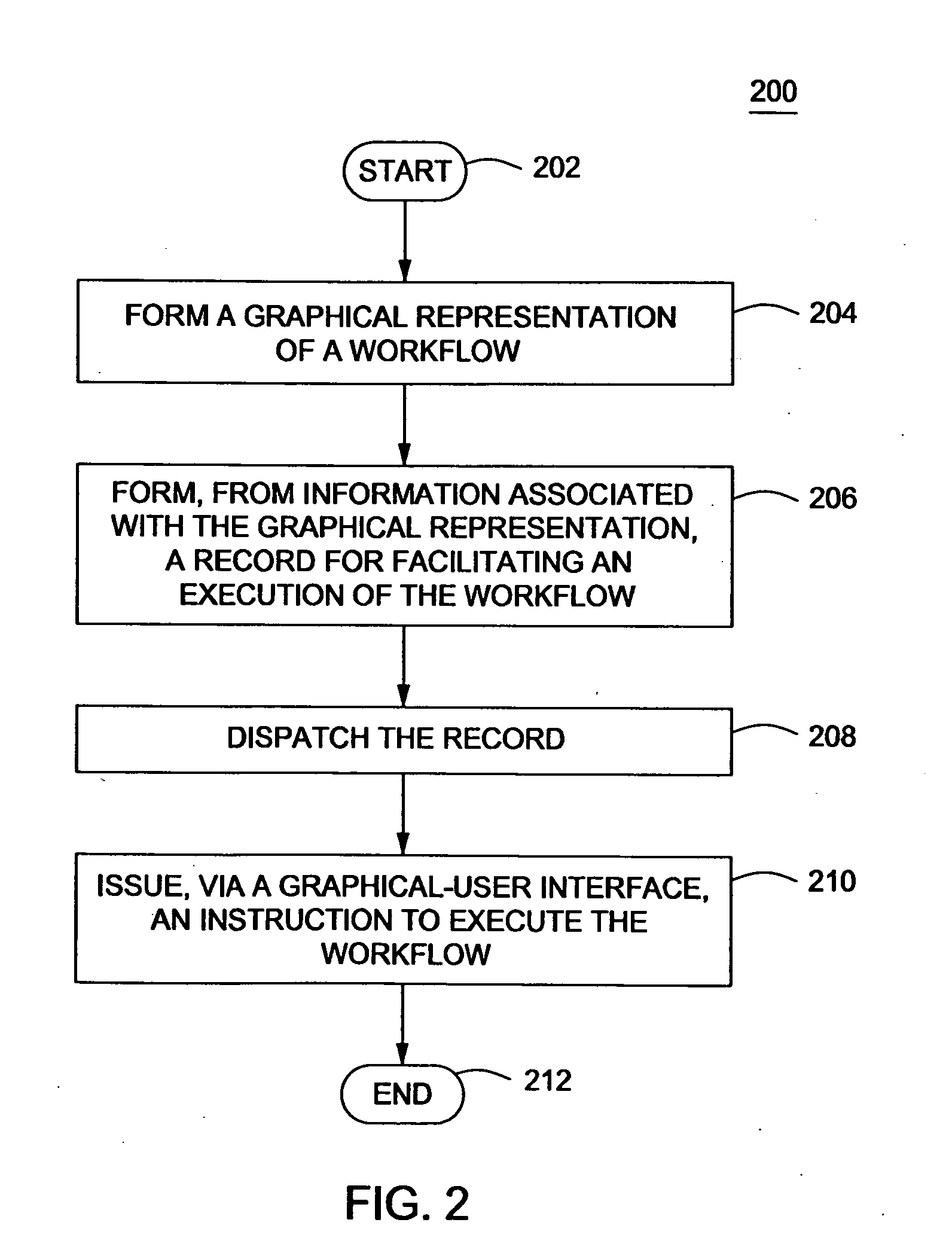
[0043]Referring now to FIG. 2, a flow diagram illustrating a flow 200 for facilitating a generation, deployment and / or execution of a workflow is shown. For convenience, the flow 200 is described with reference to the user device 100 of FIG. 1. The flow 200, however, may be carried out using other architectures as well.

[0044]The flow 200 starts at termination block 202, whereupon the processor 120 executes the GUI software 110 to form the GUI and render the display screen 124. After termination block 202, the flow 200 transitions to process block 204.

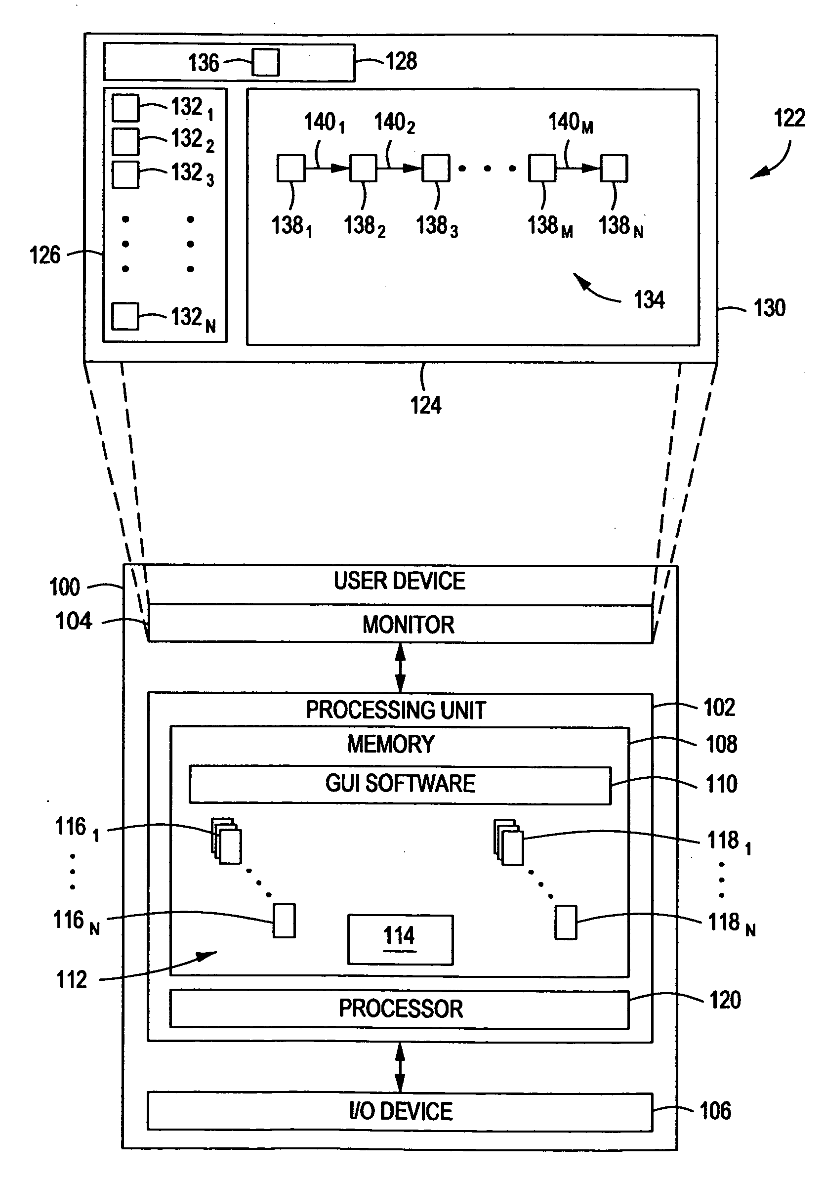
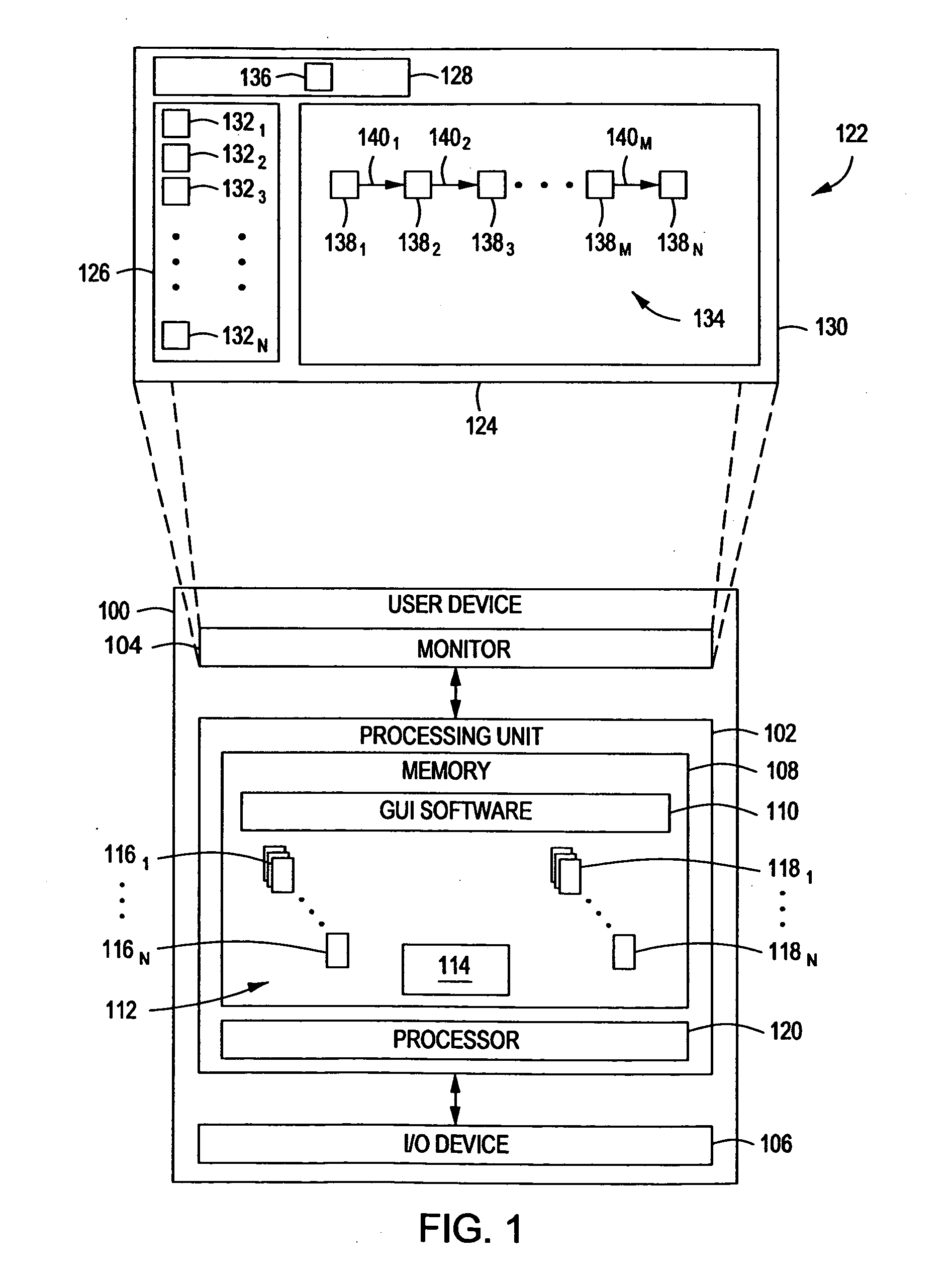
[0045]As shown in process block 204, the GUI software 110 may form the graphical workflow 134. The GUI software 110 may do so in response to one or more manipulations of the GUI by the user via the I / O device 106. For example, the GUI software 110 may render the task-widget instances 1381-138n on workflow pane 130 responsive to the I / O device 106 manipulating the GUI to select from the task widgets 1321-132n and to place (e.g., by dragg...


PUM


Abstract

A system and method for triggering deployment of a workflow are provided. The method includes issuing, to a first device (e.g., a server) from application software executing on a second device (e.g., a client computer), an instruction to execute a workflow previously deployed at the first device. The workflow is formed as a function of information associated with a graphical representation of the workflow. The application software may be, for example, software for one or more word-processing, spreadsheet, database, email, instant messenger, presentation, browser, calendar, organizer, media, image-display applications; file management programs and/or operating system shells. Alternatively, the application software may be or include a module associated with such application software. This module may include or be formed as or from one or more plug-ins, add-ons, applets, shared libraries, and/or extensions.

Description

CROSS-REFERENCE TO RELATED APPLICATIONS[0001]This application is related to the following co-pending U.S. patent application Ser. No. 11 / 853,143, filed Sep. 11, 2007, entitled “A System, Method and Graphical User Interface for Workflow Generation, Deployment and / or Execution” naming Jean-Baptiste Leonelli and Trisala Chandaria, as inventors (Attorney Docket Ref.: TEM004); which is incorporated herein by reference in its entirety for all purposes.BACKGROUND[0002]1. Field[0003]The following relates to workflow deployment and execution. More particularly, the following relates to a method, apparatus and user interface for triggering deployment and / or execution of one or more workflows.[0004]2. Related Art[0005]A company can employ one or more business processes and other workflows to carry out their core and ancillary businesses. These workflows may include, for example, a workflow to facilitate processing of information as it moves among or within any business disciplines, including p...

Claims


Application Information

Patent Timeline
Patent Type & Authority Applications(United States)
IPC IPC(8): G06F9/06
CPCG06Q10/06G06F8/34
Inventor LEONELLI, JEAN-BAPTISTECHANDARIA, TRISALA
Owner CIANMBELLA LTD
Why Eureka
Try Eureka