Magnetic latch and handle for toilet seat

a technology of latches and handles, applied in the field of magnetic latches and handles for toilet seats, can solve the problems of unsanitary environment, leave people in the dark about what, etc., and achieve the effect of improving the handle of the toilet sea

Inactive Publication Date: 2012-08-09
LOVELESS JARED
View PDF3 Cites 2 Cited by
  • Summary
  • Abstract
  • Description
  • Claims
  • Application Information

AI Technical Summary

Benefits of technology

[0009]Another object of the present invention is to provide a toilet seat handle that does not require significant changes to the general construction of a toilet seat, allowing for easy retrofit to existing toilets.
[0012]In the preferred embodiment of the present invention, the toilet seat handle includes a magnetic latch that is built into both portions of a toilet seat, the top lid and the bottom lid, in order to engage one another providing a means of lifting both lids together, with a handle for the user to manipulate positioned on the topmost surface of the top lid when in the closed position. This handle would be directly attached to the magnet in the top lid, allowing the user to manipulate the position of the magnet in the top lid in relation to the position of the magnet that is embedded in the bottom lid, resulting in the two magnets engaging one another to allow the handle to lift both lids or being separated by the user in order to lift the top lid separate of the bottom lid. Due to the nature of magnetic attractions a user can override the latch by simply pulling the two lids apart without damaging the latch, the lids, or the magnets. Keeping the handle on the topmost surface of the closed toilet seat allows the user the opportunity to inspect the handle and surrounding surface prior to using, unlike most toilet seats that require contacting an unseen surface prior to using
[0013]Furthermore, given the location of the handle on the topmost surface of the toilet seat in the closed position, the present invention would be most useful at the front edge of the top lid in order to facilitate grabbing the handle from the open position, as well as allowing for an open ended recess for the user's finger that can be easily flushed out and cleaned and offers more air flow to dry the surface.

Problems solved by technology

This method also leaves people in the dark about what they are exposing themselves to until they have already done so.
The problem is that the points where these appendages are attached to the lids still create an unsanitary environment that can harbor bacteria and become a transmission point for a myriad of germs.

Method used


Image

  • Magnetic latch and handle for toilet seat
  • Magnetic latch and handle for toilet seat
  • Magnetic latch and handle for toilet seat

Examples


Embodiment Construction

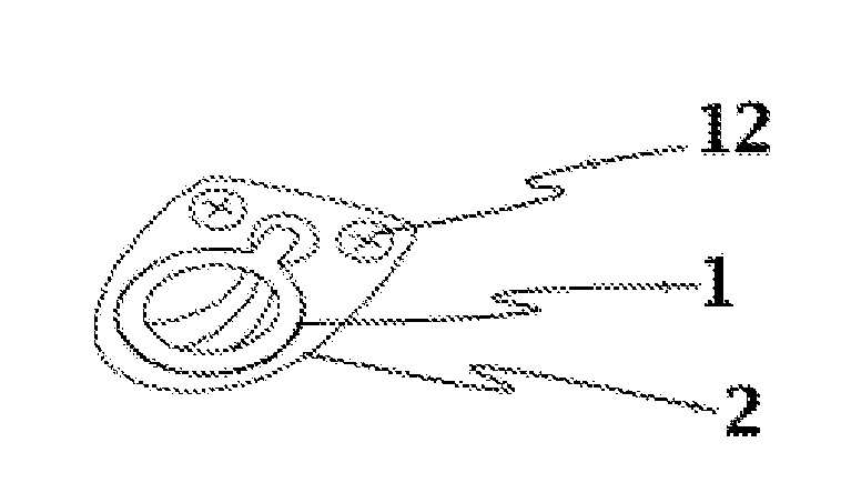
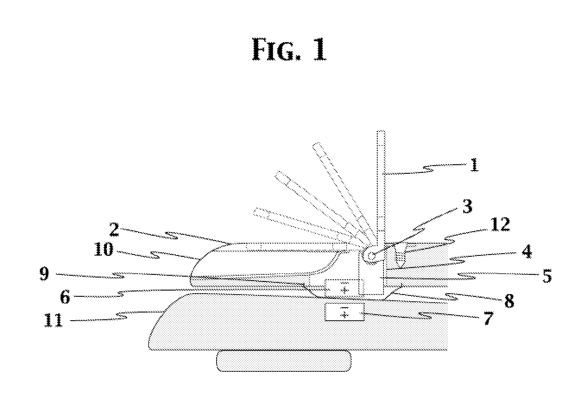
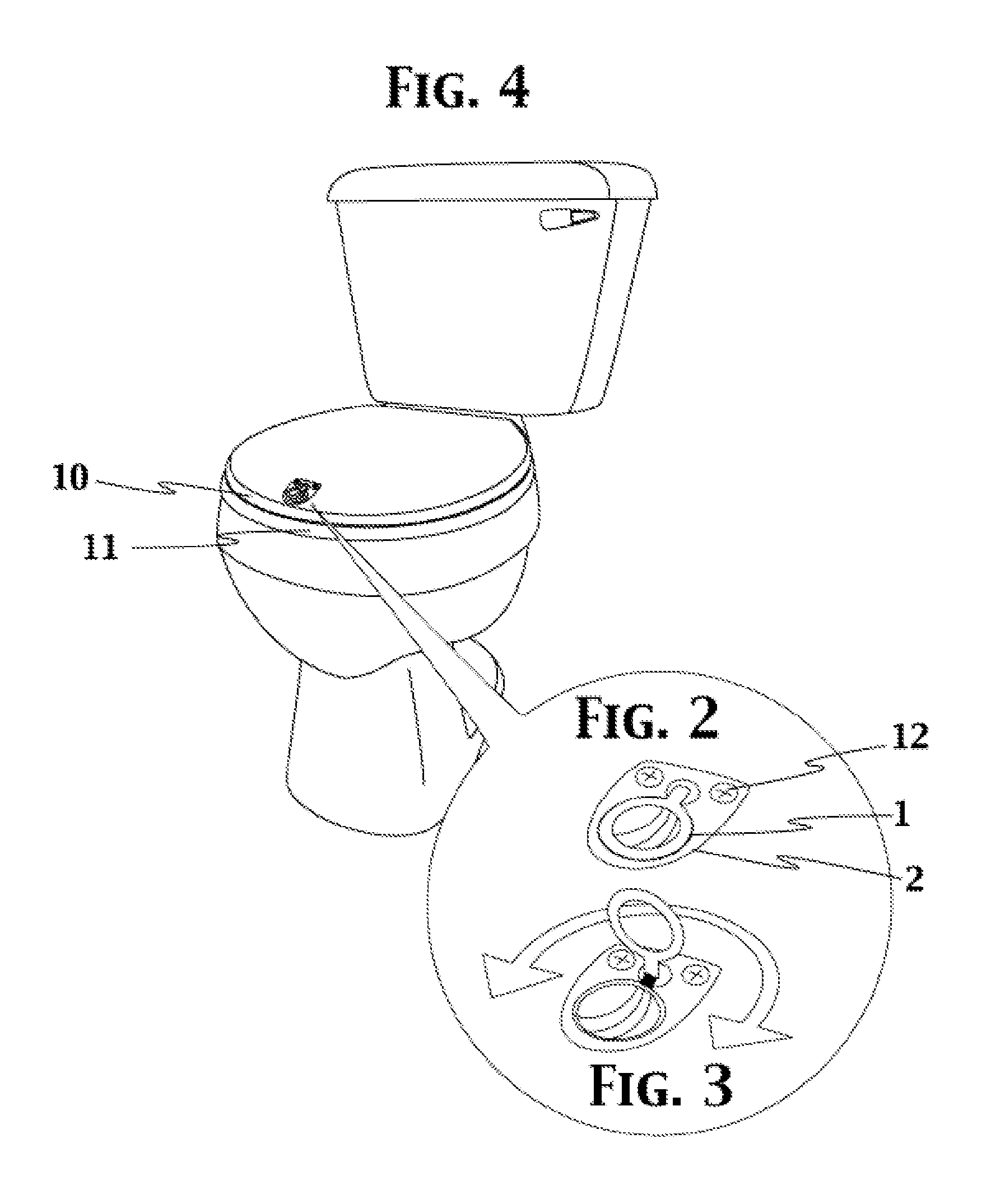
[0020]Referring now to FIG. 1 there is shown a cross sectional view of the preferred embodiment of the present invention, which is a toilet seat handle that is used to lift one or both lids of a toilet seat. This view is depicting an area in the front end of the top lid 10 of a toilet seat that has a recess for a mounting plate 2 with a finger pull 1 attached to a post 5 that connects to the top magnet 6 that is housed in an area on the bottom side of the top lid 10 of a toilet seat. This area is covered from the topside by the mounting plate 2 and on the bottom side by a flexible cover 8 that has a flange 9 designed to mate with a grooved ring on the bottom surface of the top lid 10 to cover the handle mechanism and allow for vigorous cleaning which is typical of a toilet seat. In the closed position, directly beneath this flexible cover 8 is the bottom magnet 7 that is embedded in the bottom lid 11 of the toilet seat. The top magnet 6 is situated in the top lid 10 so that the pola...


PUM


Abstract

The present invention relates to providing a more hygienic way of lifting one or both lids of a toilet seat. This is achieved through the use of a system of magnets to couple the two lids consisting of one magnet installed in both the top and bottom lid with the magnet in the top lid securely attached to a handle that is mounted on the topmost surface of the top lid where it can be manipulated by the user in order to disengage the magnets when lifting only the top lid is desired, or by simply pulling on when lifting both lids is necessary.

Description

FIELD OF THE INVENTION[0001]This application claims priority to U.S. Provisional Application Ser. No. 61 / 440,668 filed Feb. 8, 2011, which is incorporated by reference herein (including drawings). The invention relates to a magnetic latch and handle for toilet seats that can be reached on the topside of a closed toilet seat lid.BACKGROUND OF THE INVENTION[0002]The present invention relates to toilet seat handles and more particularly to a topside mounted handle that utilizes a magnetic latch to secure and lift one or both lids as necessary.[0003]The conventional toilet seat setup includes a solid surface, or top lid, that resides over a secondary surface, or bottom lid, with the center portion removed, with both surfaces, or lids, connected to a pair of hinges that are bolted to a toilet. When both surfaces are in the lowered position the bottom edge of the bottom surface rests against the top edge of the toilet bowl meaning that when a user needs to lift one or both lids he needs t...

Claims


Application Information

Patent Timeline
Patent Type & Authority Applications(United States)
IPC IPC(8): A47K13/10
CPCA47K13/105
Inventor LOVELESS, JARED
Owner LOVELESS JARED
Why Eureka
Try Eureka