Supercharge Your Innovation With Domain-Expert AI Agents!

Log Wall Connector System

a technology of connecting system and log wall, which is applied in the direction of rod connection, sheet joining, structural elements, etc., can solve the problems of creating gap between adjacent logs in the log wall, and traditional construction is usually limited to right angle corners, so as to facilitate relative sliding movement of logs

Active Publication Date: 2012-08-09
WRIGHTMAN ROBERT A
View PDF10 Cites 9 Cited by
  • Summary
  • Abstract
  • Description
  • Claims
  • Application Information

AI Technical Summary

Benefits of technology

[0011]According to one aspect of the invention, a building structure comprises a vertically extending longitudinal face, a plurality of horizontal logs extending from said longitudinal face and having an end face in abutment with the longitudinal face. An undercut channel is provided in the longitudinal face and extends along the face. At least one of the end faces has a recess aligned with the undercut channel and a spline assembly extends between the longitudinal face and the log to secure the log to the post. The spline assembly includes a key located in and extending between the undercut channel and the recess and a slide member in one of the undercut channel and the recess. The slide member co-operates with the key to facilitate relative sliding movement of the logs and the post.

Problems solved by technology

In practical use, traditional construction is usually limited to right angle corners because of the complexity of the angled notches required for non-right angle corners.
This is particularly an issue in wooden log construction because of the shrinkage of the logs as they dry.
However, in some circumstances the connection of the key to both the log and the post as shown in U.S. Pat. No. 6,050,033 may inhibit such movement and as a result a gap is created between adjacent logs in the log walls.

Method used


Image

  • Log Wall Connector System
  • Log Wall Connector System
  • Log Wall Connector System

Examples


Embodiment Construction

[0076]The description that follows and the embodiments described therein are provided by way of illustration of examples of particular embodiments of the principles of the present invention. These examples are provided for the purposes of explanation, and not of limitation, of those principles and of the invention. In the description, like parts are marked throughout the specification and the drawings with the same respective reference numerals. The drawings are not necessarily to scale and in some instances proportions may have been exaggerated in order more clearly to depict certain features of the invention.

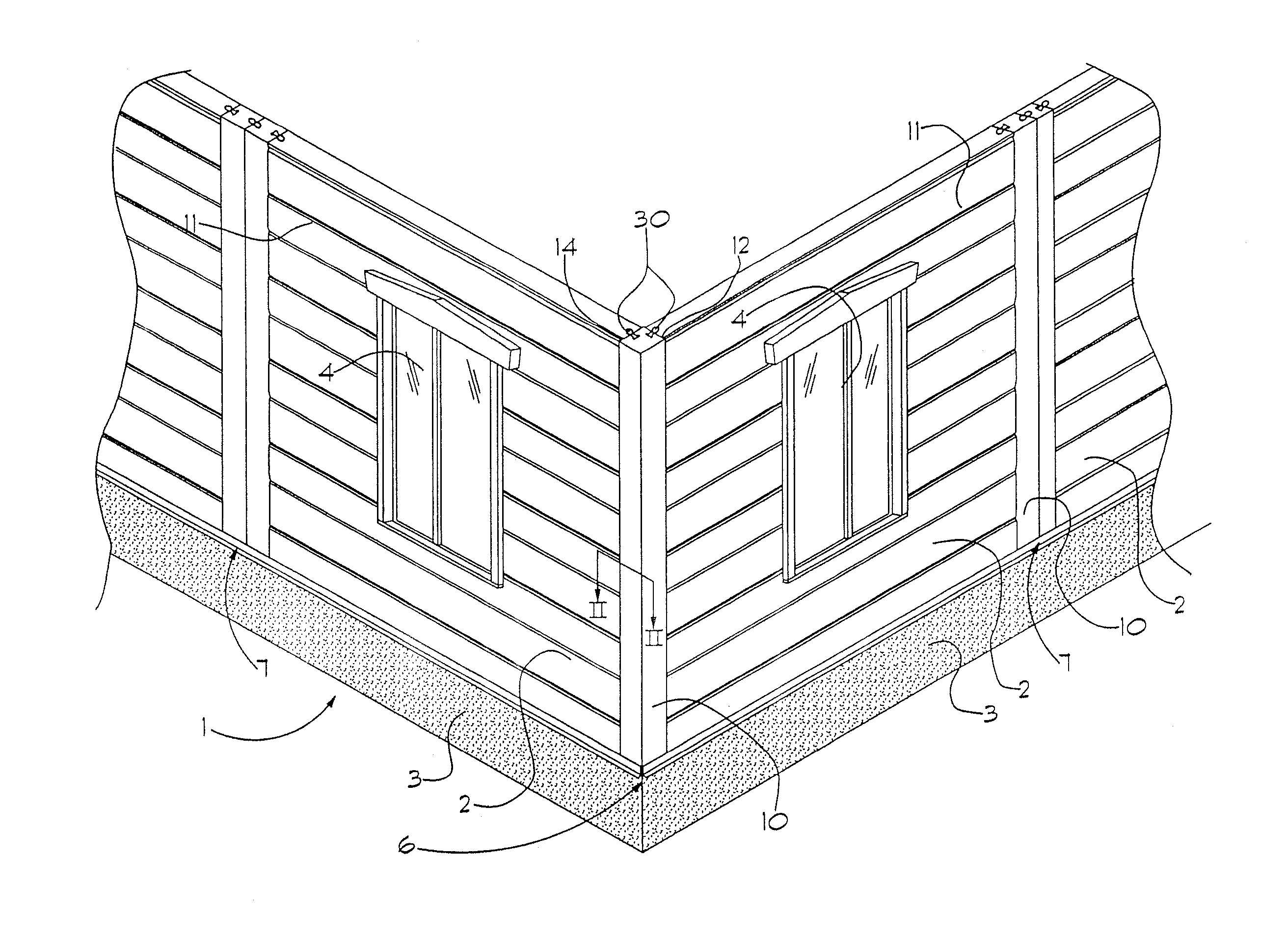
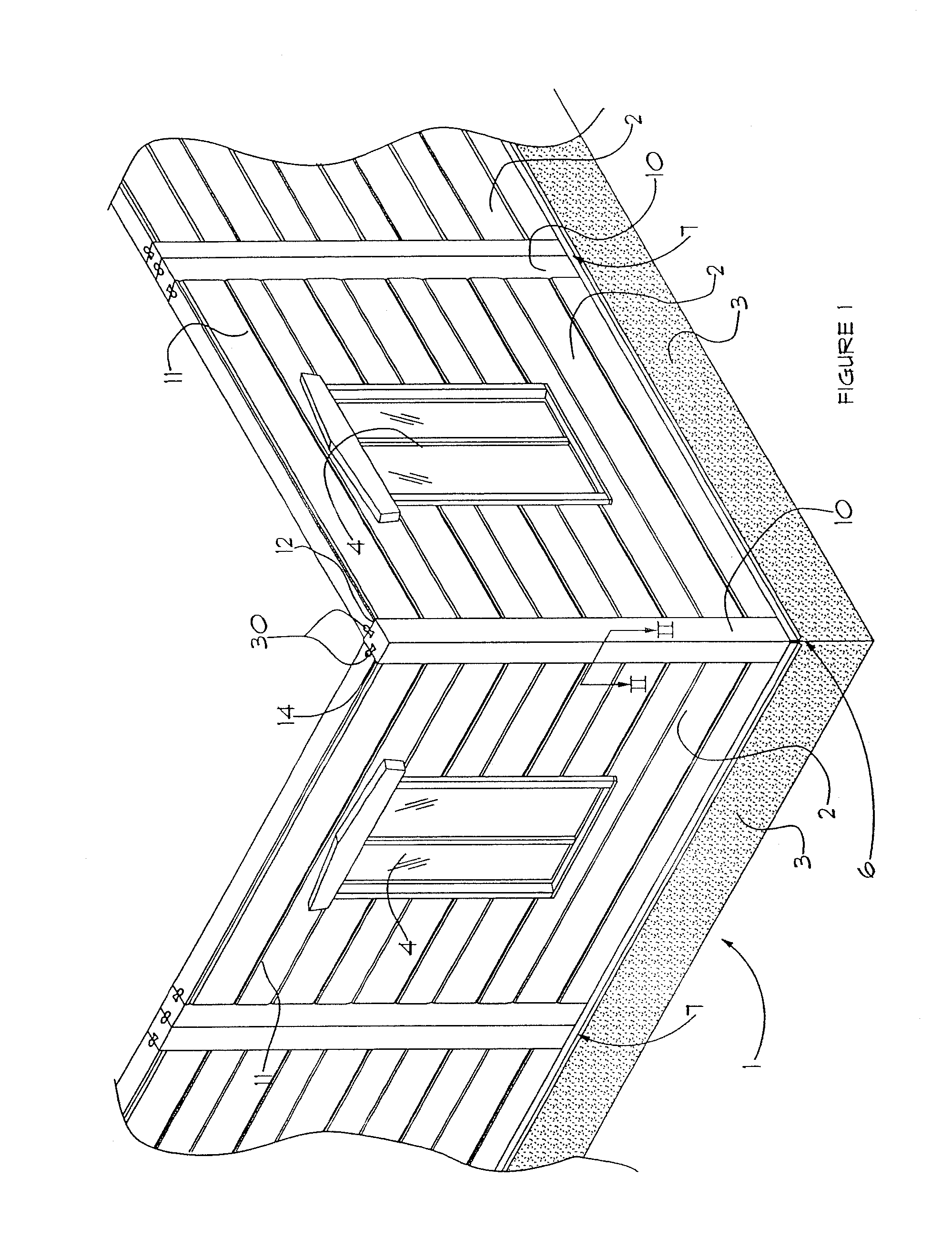
[0077]Referring therefore to FIG. 1, a building 1 includes log walls 2 that intersect at a corner 6. The log walls 2 are supported on a foundation wall 3, that may be poured concrete or laid cement block, and have openings for windows 4. The log walls 2 will support a roof or additional framed storey in a conventional manner. Each of the log walls 2 is formed from logs 11 that...


PUM


Abstract

A building structure comprises a post having a vertically extending longitudinal face. A plurality of horizontal logs extends from said longitudinal face and has an end face in abutment with said longitudinal face. The post having an undercut channel in said longitudinal face and extends along said post. At least one of said end faces has a recess aligned with said undercut channel, and a spline assembly extends between said post and said log to secure said log to said post. The spline assembly includes a key located in and extends between said channel and said recess and an insert in one of said undercut channel and said recess. The insert co operates with said key to facilitate relative sliding movement therebetween.

Description

CROSS-REFERENCE TO RELATED APPLICATIONS[0001]This application is a continuation-in-part of U.S. application Ser. No. 12 / 368,131 filed on Feb. 9, 2009, which is a continuation-in-part of U.S. application Ser. No. 11 / 892,870 filed on Aug. 28, 2007 and which also claims priority from U.S. Provisional Application No. 61 / 027,228 filed on Feb. 8, 2008, all of which are incorporated herein by reference.BACKGROUND OF THE INVENTION[0002]The present invention relates generally to wall structures and in particular to log wall structures.[0003]Log construction has been known for many decades as typified by the log cabin. For many years the logs have been notched so that at a corner, logs forming one wall of a structure can be laid on top of and at an angle alternating with logs from an intersecting wall. Although a number of materials may be used to form the “logs” used as wall members, including various types of composite materials, the wall members are typically milled from wood. The term “lo...

Claims


Application Information

Patent Timeline
Patent Type & Authority Applications(United States)
IPC IPC(8): E04B2/08E04C3/00
CPCE04B1/6137E04B1/6162F16B7/0473F16B5/0052E04B2/705
Inventor WRIGHTMAN, ROBERT A.
Owner WRIGHTMAN ROBERT A
Features
  • R&D
  • Intellectual Property
  • Life Sciences
  • Materials
  • Tech Scout
  • Unparalleled Data Quality
  • Higher Quality Content
  • 60% Fewer Hallucinations
Learn More