Three-conductor cable

a three-conductor cable and cable technology, applied in the direction of cables, insulated conductors, connection contact material materials, etc., can solve the problems of large size, difficult cable arrangement, and inability to meet the needs of compactness of vehicles, and achieve excellent cable arrangement performance, excellent compactness of whole size, and excellent cable arrangement performance

Active Publication Date: 2012-08-09
HITACHI METALS LTD
View PDF9 Cites 26 Cited by
  • Summary
  • Abstract
  • Description
  • Claims
  • Application Information

AI Technical Summary

Benefits of technology

[0022]According to one embodiment of the invention, a three-conductor cable is constructed such that it uses a dead space defined at a cable center portion when three cables are disposed in a triangular form in the cross sectional view. A first refrigerant path is formed at the dead space, it can be more compact than the prior art where the refrigerant path is separately formed

Problems solved by technology

However, even if the inventions disclosed by JP-A-2000-133058 and JP-A-2001-202837 could be applied to the feeding three cables connected to the in-wheel motor, the following problems may arise.
However, if the three cables are each provided with the tube

Method used


Image

  • Three-conductor cable
  • Three-conductor cable

Examples


embodiment

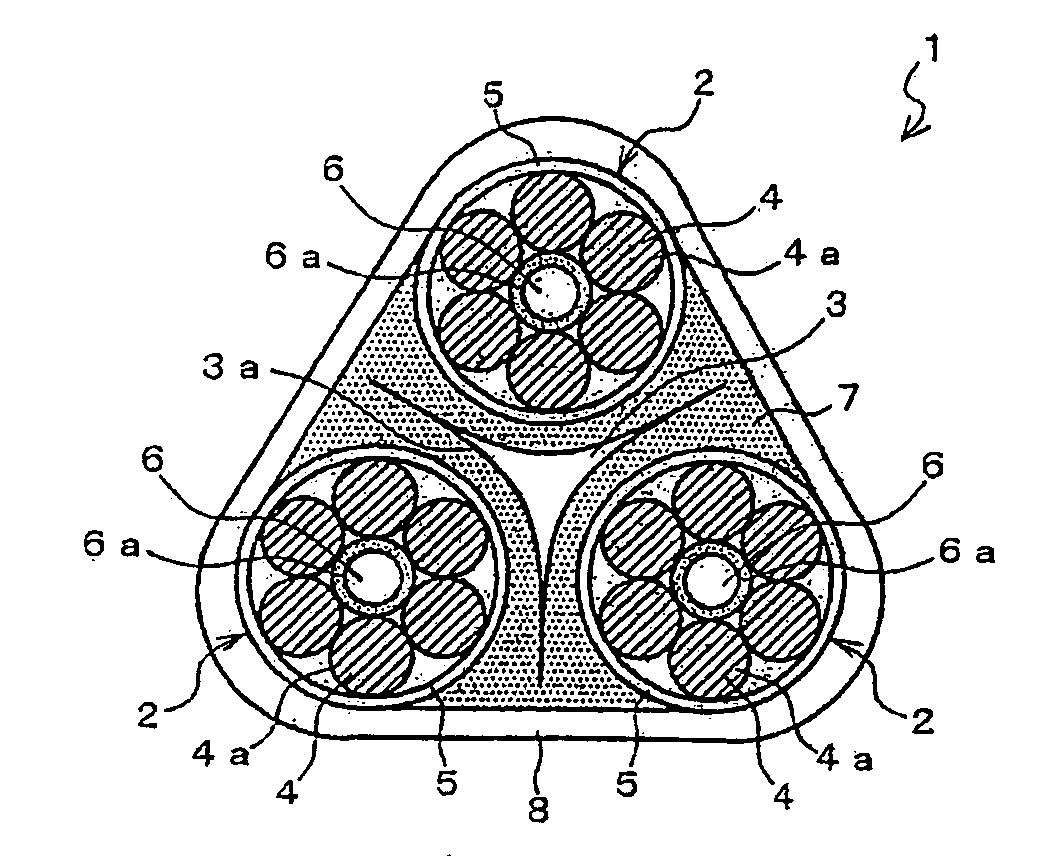
[0027]FIG. 1 is a cross sectional view showing a three-conductor cable in an embodiment according to the invention.

[0028]As shown in FIG. 1, the three-conductor cable 1 comprises three cables 2 disposed in a triangular form in a cross section thereof, and a first refrigerant path 3 for flowing a refrigerant for cooling the three cables 2.

[0029]The three cables 2 are, e.g., a feeding cable (or feeding wiring) for supplying power to an in-wheel motor installed in a vehicle wheel. In this embodiment, the three cables 2 are arranged such that three lines connecting the two adjacent centers (in the cross sectional view) of the three cables 2 form substantially an equilateral triangle in the cross section.

[0030]The three cables 2 each comprise a conductor 4 and an insulator 5 formed on the periphery of the conductor 4. In this embodiment, the conductor 4 is a twisted wire with plural wires 4a twisted each other.

[0031]Also, at the center (in the cross sectional view) of each cable 2, a sec...


PUM


Abstract

A three-conductor cable includes three cables disposed in a triangular form in a cross sectional view thereof, and a first refrigerant path at a cable center portion surrounded by the three cables along a longitudinal direction of the three cables for flowing a refrigerant for cooling the three cables therethrough. The first refrigerant path is formed along a part of each of the three cables in a cross sectional view thereof.

Description

[0001]The present application is based on Japanese patent application No. 2011-022891 tiled on Feb. 4, 2011, the entire contents of which are incorporated herein by reference.BACKGROUND OF THE INVENTION[0002]1. Field of the Invention[0003]This invention relates to a three-conductor cable used as a feeding cable etc. for an in-wheel motor.[0004]2. Description of the Related Art[0005]Heretofore, many cables (or electrically conducting path) with cooling functions are disclosed (e.g., JP-A-2000-133058, JP-A-2001-202837).[0006]In recent years, a feeding cable for an in-wheel motor (i.e., a motor enclosed in a vehicle wheel) has been increasingly researched.SUMMARY OF THE INVENTION[0007]The inventors of the invention have tried to add cooling functions to feeding three cables connected to the in-wheel motor.[0008]Because, by adding the cooling functions to the feeding three cables connected to the in-wheel motor, many merits can be obtained that heat generated from each cable can be diss...

Claims


Application Information

Patent Timeline
IPC IPC(8): H01B7/00H05K7/20
CPCH01B7/423
Inventor OKA, FUMIHITOESHIMA, HIROTAKA
Owner HITACHI METALS LTD
Why Eureka
Try Eureka