Virtual image display apparatus

a virtual image and display device technology, applied in the field of virtual image display devices, can solve the problems of difficult to increase the size of a virtual image, difficult to increase the effective pupil diameter, and not perfectly see-through, so as to reduce weight, increase safety, and perform stably and precisely

Active Publication Date: 2012-08-09
SEIKO EPSON CORP
View PDF4 Cites 194 Cited by
  • Summary
  • Abstract
  • Description
  • Claims
  • Application Information

AI Technical Summary

Benefits of technology

[0007]An advantage of some aspects of the invention is to provide a virtual image display apparatus having a simple configuration capable of increasing the size of a displayed virtual image, ensuring a large eye ring diameter, and achieving satisfactory see-through observation.

Problems solved by technology

However, since the apparatus described in JP-A-2006-3879 or any other document achieves a see-through configuration based on a pupil division method in which a light guide optical system having a light exiting aperture smaller than the size of the pupil is used, it is difficult to increase the size of a displayed virtual image.
Further, a light guide optical system having a light exiting aperture smaller than the size of the pupil is used, it is difficult to increase an effective pupil diameter (light introducing diameter that allows virtual image to be captured and also called eye ring diameter) in order to support a variety of human interpupillary distances.
Moreover, since the light exiting aperture of the light guide optical system and an enclosure are physically disposed in the vicinity of the pupil, a blind spot is produced and the resultant configuration is not perfectly see-through.

Method used


Image

  • Virtual image display apparatus
  • Virtual image display apparatus
  • Virtual image display apparatus

Examples


Embodiment Construction

[0035]A virtual image display apparatus according to an embodiment of the invention will be described below in detail with reference to the drawings.

A. Exterior Appearance of Virtual Image Display Apparatus

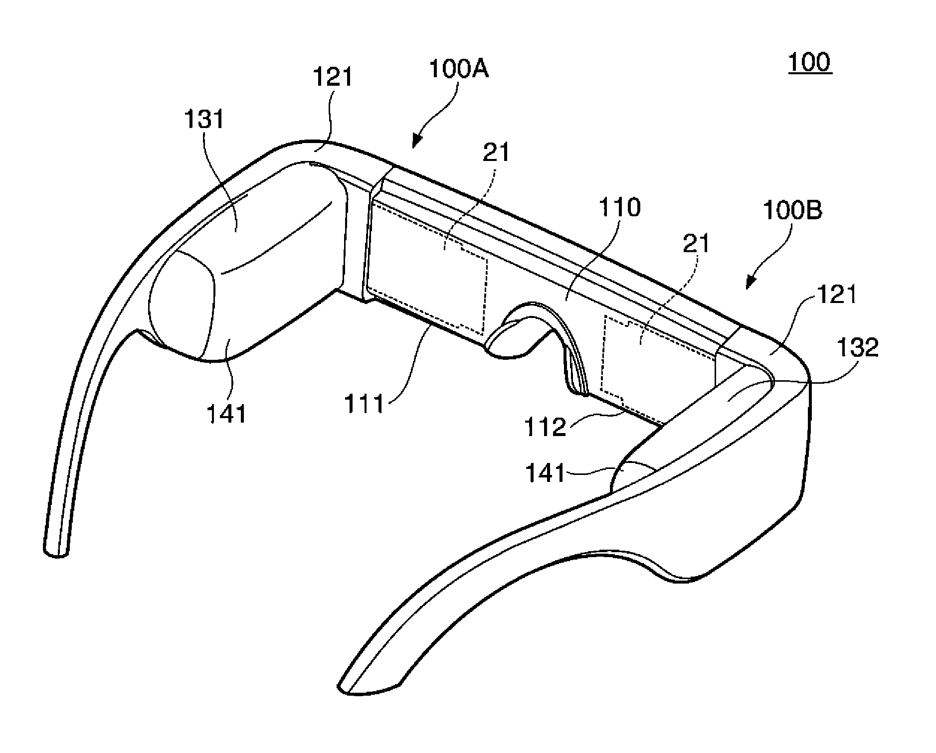
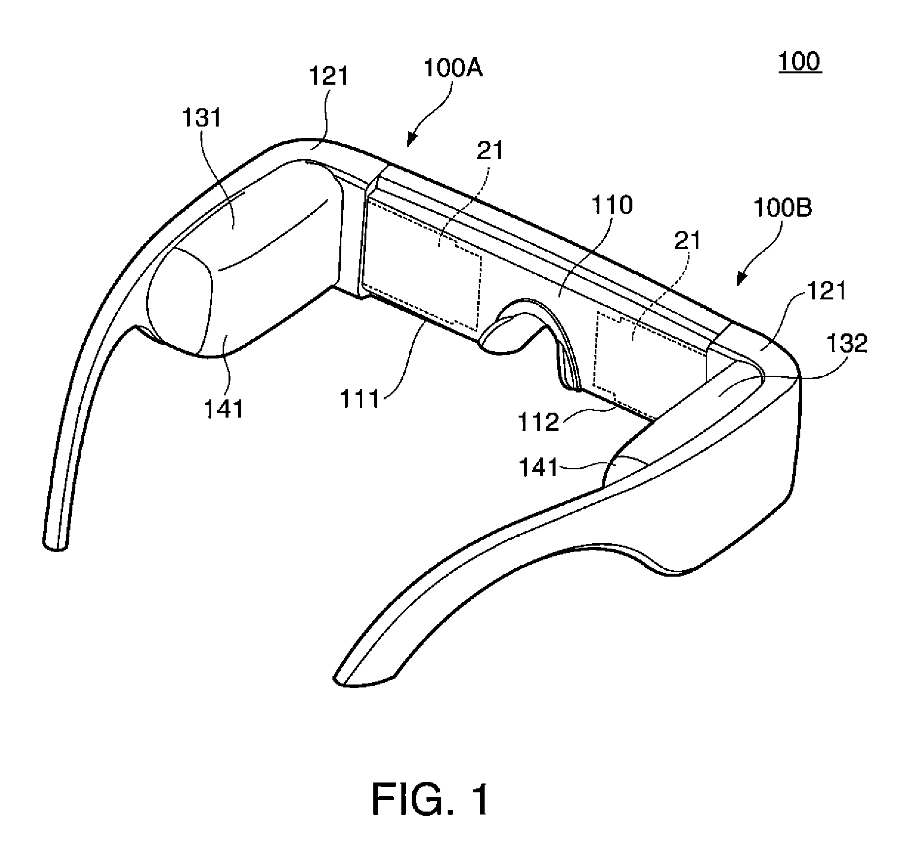
[0036]A virtual image display apparatus 100 according to an embodiment shown in FIG. 1 is a head mounted display having an eyeglass-like exterior appearance and allows a viewer who wears the virtual image display apparatus 100 to not only recognize image light in the form of virtual image but also view an outside-world image in a see-through manner. The virtual image display apparatus 100 includes an optical panel 110, which covers the front side of the eyes of the viewer, support portions 121, which support the optical panel 110, and first and second drivers 131, 132, each of which is attached to a portion extending from a exterior cover of the corresponding support portion 121 to a temple. The optical panel 110 includes a first panel portion 111 and a second panel portion 112, a...


PUM


Abstract

A support frame includes a light transmissive portion that is combined with a light guide member to form a see-through portion. The support frame assembled with the light guide member for image light observation therefore allows see-through observation of an outside-world object through the see-through portion. Further, providing the light transmissive portion in the support frame can increase the strength of the support frame while reducing the weight of the light guide member.

Description

BACKGROUND[0001]1. Technical Field[0002]The present invention relates to a virtual image display apparatus, such as a head mounted display worn on the head.[0003]2. Related Art[0004]As a virtual image display apparatus that allows formation and observation of a virtual image, such as a head mounted display, a variety of apparatuses that guides image light from a display device through a light guide plate to the pupils of a viewer have been proposed in recent years.[0005]For a virtual image display apparatus of this type, see-through optical systems have been proposed to superimpose image light and external light (see JP-A-2006-3879 and JP-A-2010-224473).[0006]However, since the apparatus described in JP-A-2006-3879 or any other document achieves a see-through configuration based on a pupil division method in which a light guide optical system having a light exiting aperture smaller than the size of the pupil is used, it is difficult to increase the size of a displayed virtual image....

Claims


Application Information

Patent Timeline
Patent Type & Authority Applications(United States)
IPC IPC(8): G02B27/01
CPCG02B27/0172G02B6/00
Inventor MIYAO, TOSHIAKITAKAGI, MASAYUKITOTANI, TAKAHIROKOMATSU, AKIRATAKEDA, TAKASHI
Owner SEIKO EPSON CORP
Why Eureka
Try Eureka