Method for Low Memory Footprint Compressed Video Decoding

Active Publication Date: 2012-08-09
TEXAS INSTR INC
View PDF4 Cites 20 Cited by
  • Summary
  • Abstract
  • Description
  • Claims
  • Application Information

AI Technical Summary

Benefits of technology

[0008]This invention exploits situations where a current group of pictures requires less than the maximum number of frame buffers for decoding. This could occur due to the mix of frame types (I, P and B) in that g

Problems solved by technology

This is a big problem especially for High Definition (HD) decoding due to the large frame size.
This is a huge amount of memory.
Many systems will not have this much free memory

Method used


Image

  • Method for Low Memory Footprint Compressed Video Decoding
  • Method for Low Memory Footprint Compressed Video Decoding
  • Method for Low Memory Footprint Compressed Video Decoding

Examples


Example

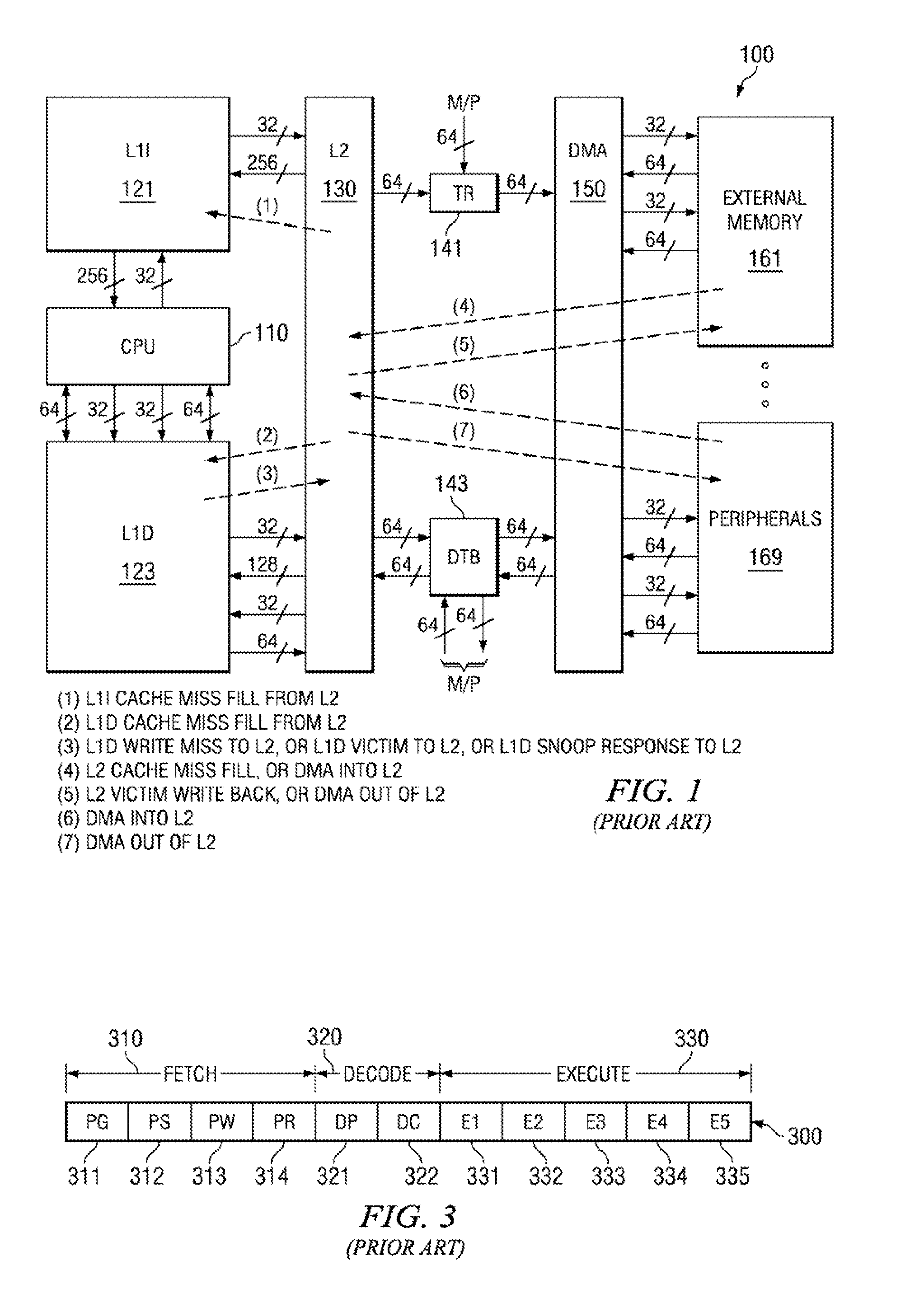
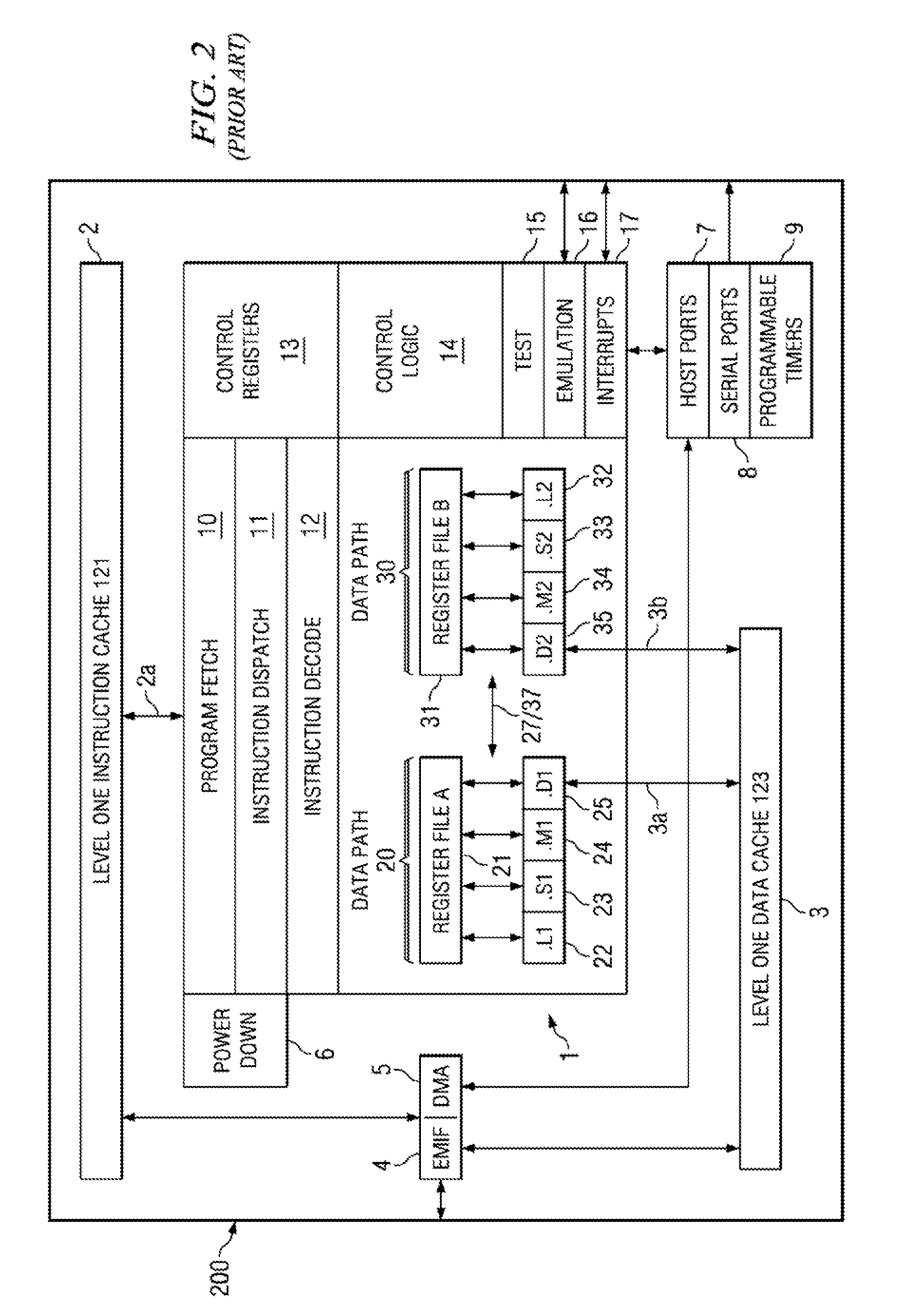
[0018]FIG. 1 illustrates the organization of a typical digital signal processor system 100 to which this invention is applicable (prior art). Those skilled in the art would realize that this is an example only and that this invention can be practiced on a varied of programmable digital data processors having different organization than shown in FIGS. 1 to 4. Digital signal processor system 100 includes central processing unit core 110. Central processing unit core 110 includes the data processing portion of digital signal processor system 100. Central processing unit core 110 could be constructed as known in the art and would typically includes a register file, an integer arithmetic logic unit, an integer multiplier and program flow control units. An example of an appropriate central processing unit core is described below in conjunction with FIGS. 2 to 4.

[0019]Digital signal processor system 100 includes a number of cache memories. FIG. 1 illustrates a pair of first level caches. L...


PUM


Abstract

This invention is a method of memory saving in compressed video decoding. For each group of pictures the method determines whether less than the maximum number N reference frames are needed for decoding. If so, then a memory is configuring for the needed number M reference frames less than N. If not, the memory is configured for N reference frames. The group of pictures is decoding the group of pictures using the configured number of reference frames.

Description

CLAIM OF PRIORITY[0001]This application claims priority under 35 U.S.C. 119(e)(1) to U.S. Provisional Application No. 61 / 416,802 filed Nov. 24, 2010.TECHNICAL FIELD OF THE INVENTION[0002]The technical field of this invention is video decoding.BACKGROUND OF THE INVENTION[0003]A typical H.264 universal decoder implementation needs a high dual data rate (DDR) memory footprint. This is primarily due to the large amount of memory needed for storing reference frames and co-located macroblock information required for decoding bidirectionally predicted (B) frame macroblocks. This is a big problem especially for High Definition (HD) decoding due to the large frame size.[0004]A H.264 decoder typically requires multiple frames to be stored in a decoded picture buffer (DPB) as reference frames. The decoder may require up to N frames depending on the resolution. In addition many frames worth of macroblock information have to be stored in the DDR memory. These are co-located macroblock informatio...

Claims


Application Information

Patent Timeline
IPC IPC(8): H04N7/26
CPCH04N19/61H04N19/573H04N19/44H04N19/132
Inventor PRASAD, KESHAVASHASTRY, PAVAN VENKATA
Owner TEXAS INSTR INC
Why Eureka
Try Eureka