Hydrostatic transmission device for a heavy vehicle

a transmission device and heavy vehicle technology, applied in the direction of belt/chain/gearing, coupling, belt control, etc., can solve the problems of limited hydrostatic braking effect and inability to be desirable in other situations, and achieve the effect of high fluid flow ra

Inactive Publication Date: 2012-12-18
POCLAIN HYDRAULICS IND
View PDF19 Cites 18 Cited by
  • Summary
  • Abstract
  • Description
  • Claims
  • Application Information

AI Technical Summary

Benefits of technology

[0013]The effectiveness of hydrostatic braking is thus increased due to the restriction in the flow of fluid through the bypass link.
[0017]When in its free configuration, the constriction valve makes it possible for the transmission to operate normally at increased speed, while at least one motor is bypassed, whereas said constriction valve can be placed in its constricted configuration when hydrostatic braking is necessary at a level such that the fluid pressure in the bypass link exceeds the pressure threshold.
[0019]Advantageously, the apparatus further comprises a check valve that is disposed in parallel with the constriction valve so as to allow free flow in the bypass link, in the non-preferred direction of travel. It is also advantageous for the apparatus to further comprise means for detecting the direction of travel of the vehicle and for preventing the constriction valve from going into said constricted configuration when the non-preferred direction of travel is detected.
[0023]This applies particularly while the vehicle is travelling in its non-preferred direction (in reverse). The connection configuration of the check valve then makes it possible to obtain the desired fluid flow rate in reverse, with automatic operation that is controlled hydraulically.

Problems solved by technology

However, when the bypass valve is in its increased-speed position, both of the main orifices of the bypassed motor are connected to the discharge main duct, so that the hydrostatic braking has no effect on that motor.
Therefore the effectiveness of hydrostatic braking is limited.
For example, it might be desired to enable increased hydrostatic braking to take place under particular vehicle load conditions, or under particular conditions regarding distribution of load on the axles, and / or under particular travel conditions, whereas such a possibility might not be desirable in other situations.

Method used


Image

  • Hydrostatic transmission device for a heavy vehicle
  • Hydrostatic transmission device for a heavy vehicle
  • Hydrostatic transmission device for a heavy vehicle

Examples


Embodiment Construction

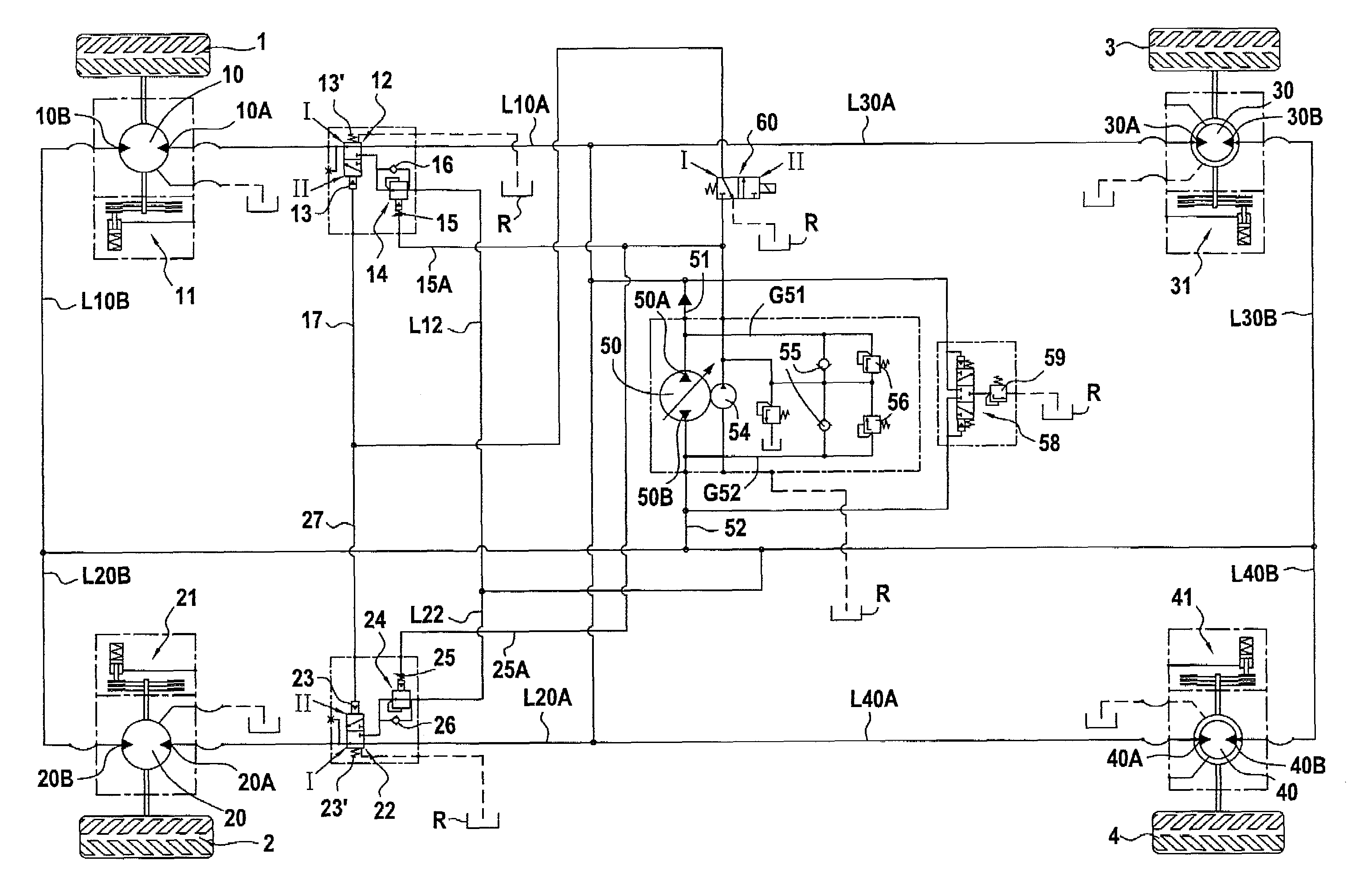
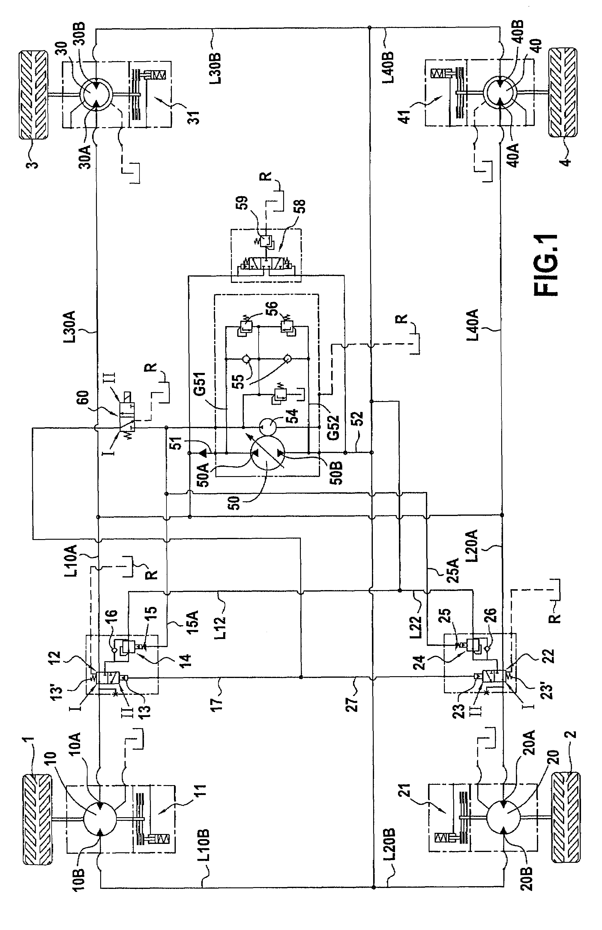
[0035]The vehicle driven by the apparatus whose hydraulic circuit is shown in FIG. 1 has two drive axles that are situated one behind the other in the direction of travel. In this example, each of the axles is provided with two wheels, respectively 1 and 2 for the first axle and 3 and 4 for the second axle. The wheels are coupled to respective ones of the motors 10, 20, 30, 40. In this example, each of the motors 10 and 20 of the wheels 1 and 2 is a motor having a single cylinder capacity, whereas each of the motors 30 and 40 of the wheels 3 and 4 is a motor having two cylinder capacities and having a cylinder capacity selector that is specific to it.

[0036]The circuit includes a main hydraulic pump 50 having two orifices, respectively 50A and 50B, and having a variable delivery rate.

[0037]The circuit also includes two main ducts, respectively a main duct 51 connected to the orifice 50A, and a main duct 52 connected to the orifice 50B. In a manner known per se, the apparatus includes...


PUM


Abstract

A hydrostatic transmission including a main pump, two main ducts serving respectfully as feed and as discharge for first and second hydraulic motors that serve to drive disposed one after the other. A bypass valve can take up a reduced-speed position in which the feed main orifices are connected to the discharge main duct, and an increased-speed position in which one of the motors is bypassed, the feed main orifice of the motor being connected to the discharge main duct via a bypass link, while the other main orifices continue to have their respective links. The apparatus further includes a constriction suitable for being activated to restrict the flow of fluid through the bypass link.

Description

BACKGROUND OF THE INVENTION[0001]The present invention relates to hydrostatic transmission apparatus for a vehicle having at least two drive members disposed one after the other in the direction of travel of said vehicle, the apparatus comprising at least two hydraulic motors suitable for driving respective ones of said drive members, each hydraulic motor having two main orifices serving respectively as feed and as discharge in a preferred direction of travel of the vehicle, a main hydraulic pump connected to two main ducts that serve respectively as feed and as discharge in the preferred direction, and a bypass valve suitable for taking up a reduced-speed position in which the feed main orifices of the motors are connected to the feed main duct, while the discharge main orifices are connected to the discharge main duct, and an increased-speed position in which at least one motor is bypassed, the feed main orifice of said motor being connected to the discharge main duct via a bypass...

Claims


Application Information

Patent Timeline
Patent Type & Authority Patents(United States)
IPC IPC(8): B60K17/10B60K17/356F16H61/40F16H61/4052F16H61/4157F16H61/444
CPCB60K17/10B60K17/356F16H61/4052F16H61/4157F16H61/444B60K7/0015
Inventor HEREN, JEANLUCIENNE, PHILIPPEPRIGENT, ANDRED'HERSIGNERIE, CYRILLE
Owner POCLAIN HYDRAULICS IND
Why Eureka
Try Eureka