Optical switch

a technology of optical switch and end face, applied in the field of optical switch, can solve the problems of term reliability, multiple reflections between the connecting surfaces, and significant insertion loss, and achieve the effect of preventing the damage to the respective end fa

Inactive Publication Date: 2012-08-09
HITACHI METALS LTD
View PDF3 Cites 16 Cited by
  • Summary
  • Abstract
  • Description
  • Claims
  • Application Information

AI Technical Summary

Benefits of technology

[0012]Accordingly, it is an object of the present invention to provide an optical switch, which can prevent damage to respective end faces of facing optical fibers due to the repetition of switching, prevent multiple reflections between respective connecting surfaces of facing connectors, and suppress an increase in insertion loss, and which is easy to be produced.
[0017]a spacer mechanism for preventing the respective end faces of the facing optical fibers held in the first connector and the second connector from contacting each other, or from contacting the connecting surface of the second connector and the connecting surface of the first connector, respectively.
[0028]According to the embodiment of the invention, the spacer mechanism is included, so that the respective end faces of the facing optical fibers held in the first connector and the second connector are prevented from contacting each other, or from contacting the connecting surface of the second connector and the connecting surface of the first connector, respectively. This spacer mechanism can prevent the damage to the respective end faces of the facing optical fibers even due to the repetition of switching.

Problems solved by technology

However, when the optical signals are spatially propagated in the spacing between the respective connecting surfaces of the facing connectors, there is the problem in that multiple reflections occurs between the connecting surfaces in the case of using the spacing of the order of several micrometers.
On the other hand, there is another problem in that the insertion loss is significant in the case of using the spacing of the order of several tens of micrometers.
However, in this conventional method, there is a problem with long-term reliability, since the refractive index matching material is likely to be dry, or air bubbles are likely to be produced in the refractive index matching material by the sliding during switching.
However, the control of the spacing is not easy, since the spacing is as micro as on the order of several micrometers to several tens of micrometers.

Method used


Image

  • Optical switch
  • Optical switch
  • Optical switch

Examples


Embodiment Construction

[0052]Below is described a preferred embodiment according to the invention, in conjunction with the accompanying drawings.

[0053](Optical Switch 10)

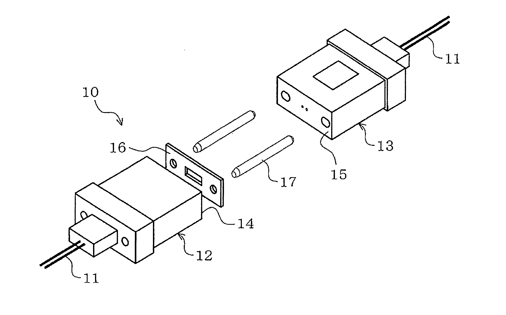
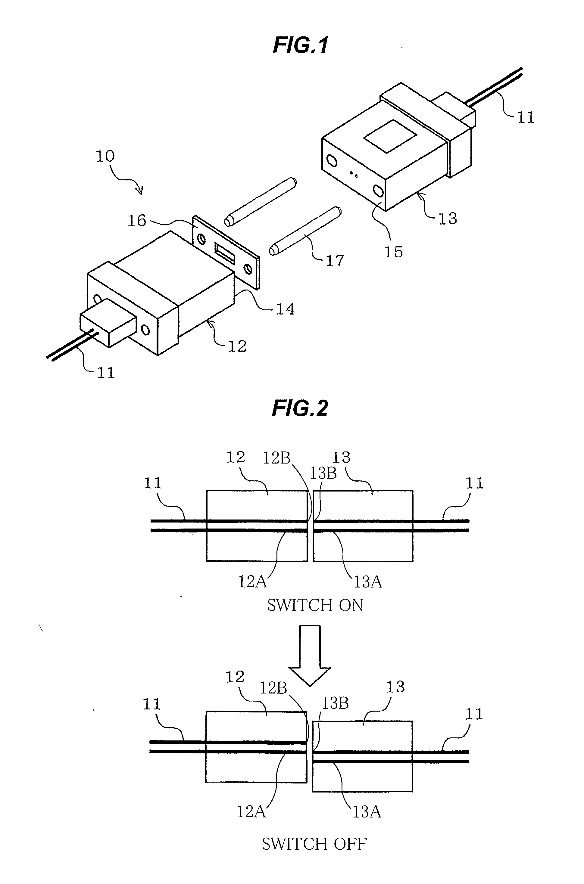
[0054]FIGS. 1 and 2 show a perspective view showing an optical switch 10 in the preferred embodiment according to the invention.

[0055]As shown in FIGS. 1 and 2, the optical switch 10 in this embodiment includes a first connector 12 for holding an end 12A of at least one optical fiber (in FIG. 1, two optical fibers) 11 and an exposed end face 12B of the at least one optical fiber 11, a second connector 13 for holding respective ends 13A of at least two optical fibers (in FIG. 1, two optical fibers) 11 and respective exposed end faces 13B of the at least two optical fibers 11, and a sliding mechanism (not shown) whereby respective connecting surfaces 14 and 15 of the first connector 12 and the second connector 13 with the respective exposed end faces 12B, 13B of the optical fibers 11 at the connecting surfaces 14 and 15 face each other with...


PUM


Abstract

An optical switch includes a first connector holding an end of at least one optical fiber and a second connector holding respective ends of at least two optical fibers. The optical switch further includes a sliding mechanism faces a connecting surface of the first connector and a connecting surface of the second connector each other, to optically connect between the at least one optical fiber held in the first connector and one of the at least two optical fibers held in the second connector, and slides the connecting surface of the first connector and the connecting surface of the second connector relative to each other with keeping a facing state, and a spacer mechanism for preventing the respective end faces of the facing optical fibers held in the first and second connectors from contacting each other, or from contacting the connecting surfaces of the first and second connectors, respectively.

Description

[0001]The present application is based on Japanese patent application No. 2011-026309 filed on Feb. 9, 2011, the entire contents of which are incorporated herein by reference.BACKGROUND OF THE INVENTION[0002]1. Field of the Invention[0003]This invention relates to an optical switch for optical transmission line switching. In particular, it relates to an optical switch which switches an optical transmission line by sliding together respective connecting surfaces of facing connectors which have respective exposed end faces of optical fibers.[0004]2. Description of the Related Art[0005]Some optical switches for optical transmission line switching have been configured to switch an optical transmission line by sliding together respective connecting surfaces of facing connectors which have respective exposed end faces of optical fibers. This sliding mechanism for the optical transmission line switching has used e.g. a solenoid, which has been miniaturized in recent years.[0006]In the opti...

Claims


Application Information

Patent Timeline
Patent Type & Authority Applications(United States)
IPC IPC(8): G02B6/35
CPCG02B6/3508G02B6/3885G02B6/3822
Inventor SUZUKI, KANAKO
Owner HITACHI METALS LTD
Why Eureka
Try Eureka