

Cold Start Valve
a cold start and valve technology, applied in the direction of rotary clutches, couplings, fluid couplings, etc., can solve the problems that the demand for starting conditions may become a more critical challenge for all, and achieve the effect of reducing the parasitic load on the engine, improving the conditions, and significantly lowering the parasitic load
- Summary
- Abstract
- Description
- Claims
- Application Information
AI Technical Summary
Benefits of technology
Problems solved by technology
Method used
Image

Examples
Embodiment Construction
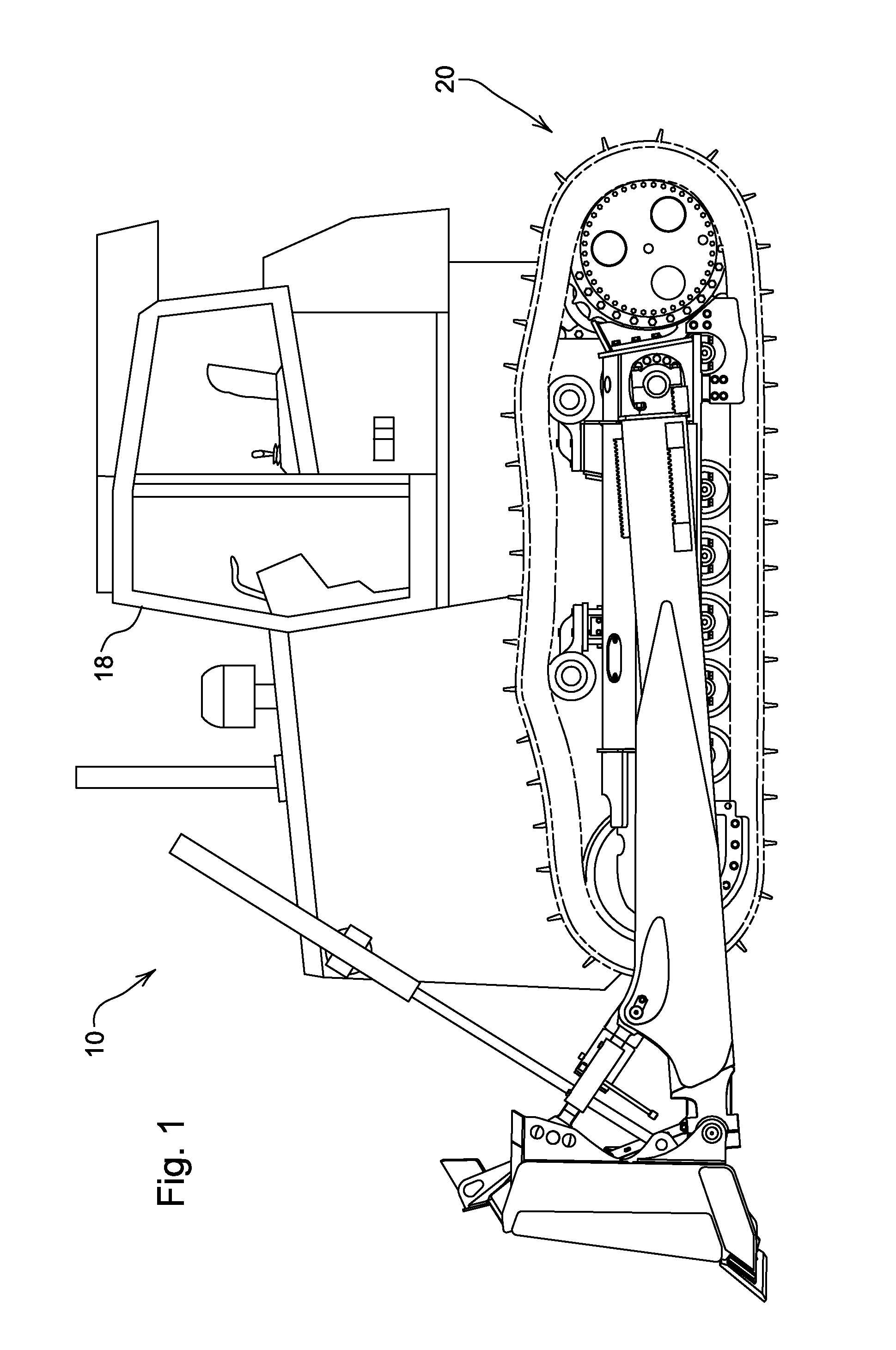
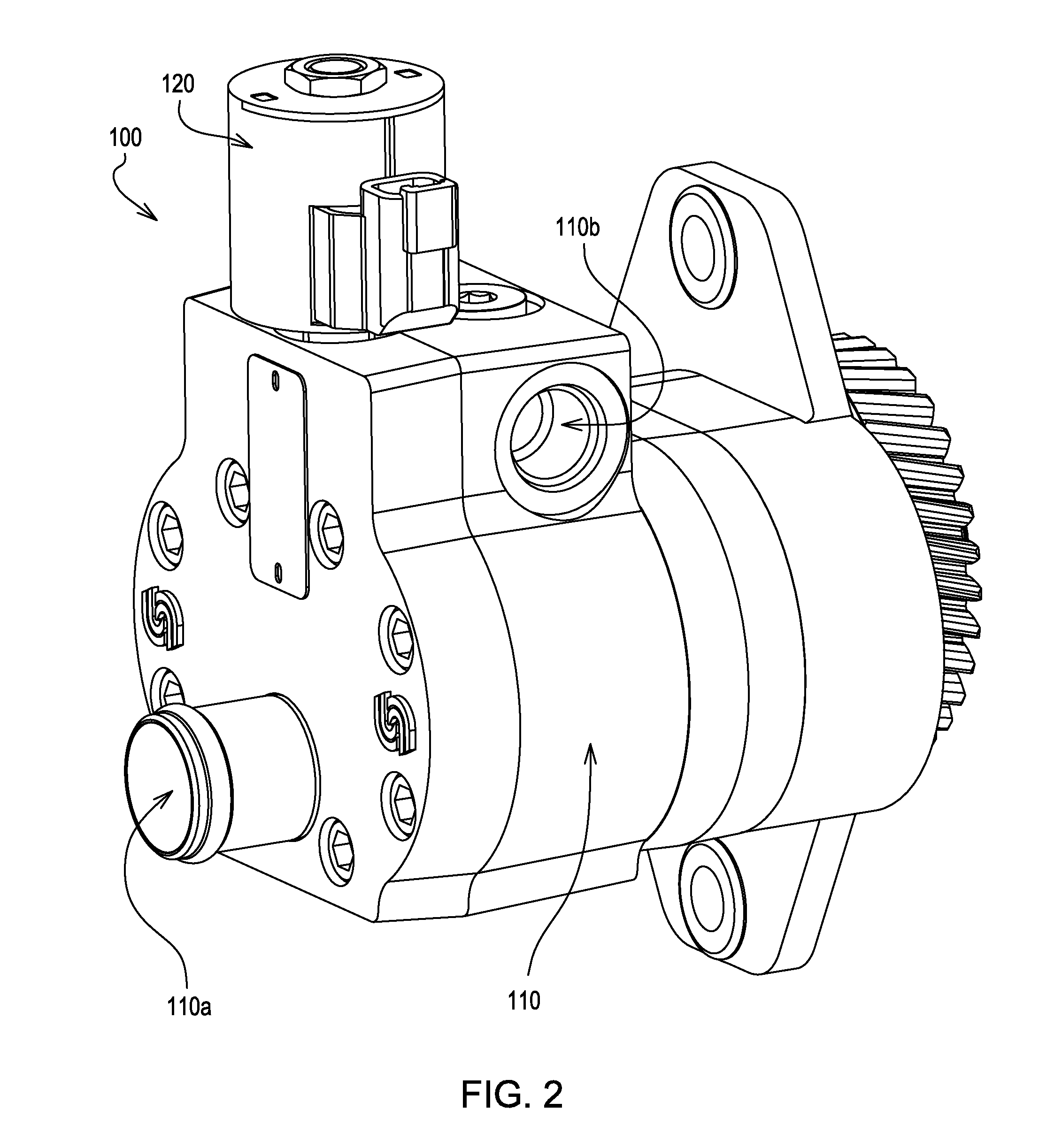
[0008]FIG. 1 illustrates a work vehicle 10, having a cab 18 and ground engaging means 20, that may incorporate the invention for the purpose of improving cold starts. In such vehicles there may be many parasitic hydraulic loads, e.g., pumps for hydraulic fans, hydrostatic charge pumps, etc. Parasitic hydraulic loads may be significantly reduced via the use of unloader valves to relieve hydraulic loads in areas where functionality requiring such hydraulic loads may be, at the time, non-essential. FIG. 2 illustrates an exemplary integrated hydraulic fan pump 100 having a pump portion 110 and an unloader valve portion 120. While unloading may be accomplished in a non-integrated fashion, such integration may save valuable space via its compactness, increase reliability via reducing the number of exposed and connected parts, and increase efficiency via a reduction in the travel distance of hydraulic oil.
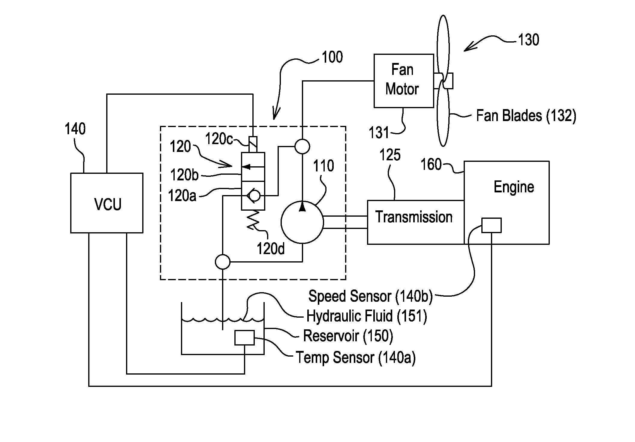
[0009]FIG. 3, is an illustration of a system showing an exemplary embodiment of the i...
PUM
 Abstract
Description
Claims
Application Information