Constant-current-drive LED module device

Active Publication Date: 2012-08-16
AIRTEC SYST CO LTD
View PDF14 Cites 11 Cited by
  • Summary
  • Abstract
  • Description
  • Claims
  • Application Information

AI Technical Summary

Benefits of technology

[0017]Further, another embodiment of the present invention is directed to a constant-current-drive LED module device capable of preventing degradation in light efficiency due to AC LED operation characteristics according to the input of an AC power sour

Problems solved by technology

In particular, as the LED demanding high power requires large drive current (generally, 350 mA or more), the LED generates a significant amount of heat and as a result, has degradation in luminance larger than the LED driven with low power.
However, the PWM scheme requires electronic components, which leads to an increase in manufacturing costs.
As described above, a power factor may be low, total harmonic distortion (THD) may be increased, and a flicker phenomenon may excessively occur, due to operating characteristics of the

Method used


Image

  • Constant-current-drive LED module device
  • Constant-current-drive LED module device
  • Constant-current-drive LED module device

Examples


first embodiment

[0052]FIG. 5 is a circuit diagram of a constant-current-drive unidirectional LED module device in accordance with the present invention.

[0053]A constant-current-drive unidirectional LED module device in accordance with an embodiment of the present invention is configured to include a rectifier 320 receiving and rectifying a commercial alternating-current power source 310; a unidirectional LED module unit 330 connected to one end of the rectifier 320; a constant current unit 340 connected to the other end of the LED module unit 330 and the rectifier 320 to provide constant current.

[0054]The constant current unit 340 in accordance with the embodiment of the present invention includes a switching unit341 connected between the LED module unit 330 and the other end of the rectifier 320 and being switched using pulsating current output from the rectifier 320, a control voltage output unit 342 detecting load current flowing in the unidirectional LED module unit 330 and converting switching...

fourth embodiment

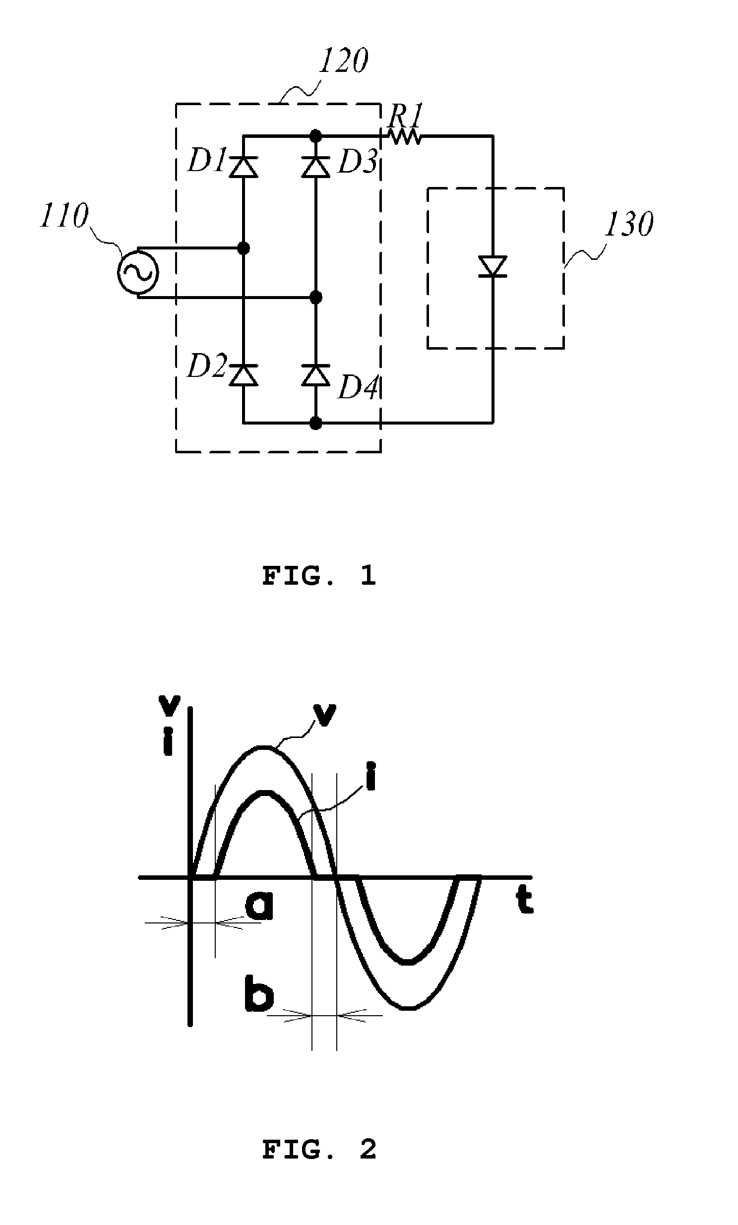
[0070]FIG. 9 is a voltage and current waveform diagram of a constant-current-drive unidirectional LED module device in accordance with the present invention. In accordance with the embodiment of the present invention, the constant-current-drive unidirectional LED module device has the LED operating period having wider than that of the circuit in accordance with the related art of FIG. 1 to increase the active power, thereby improving the power factor (PF) and has the larger root mean square value of the fundamental wave than that of the circuit in accordance with the related art of FIG. 1, thereby improving the total harmonic distortion (THD).

fifth embodiment

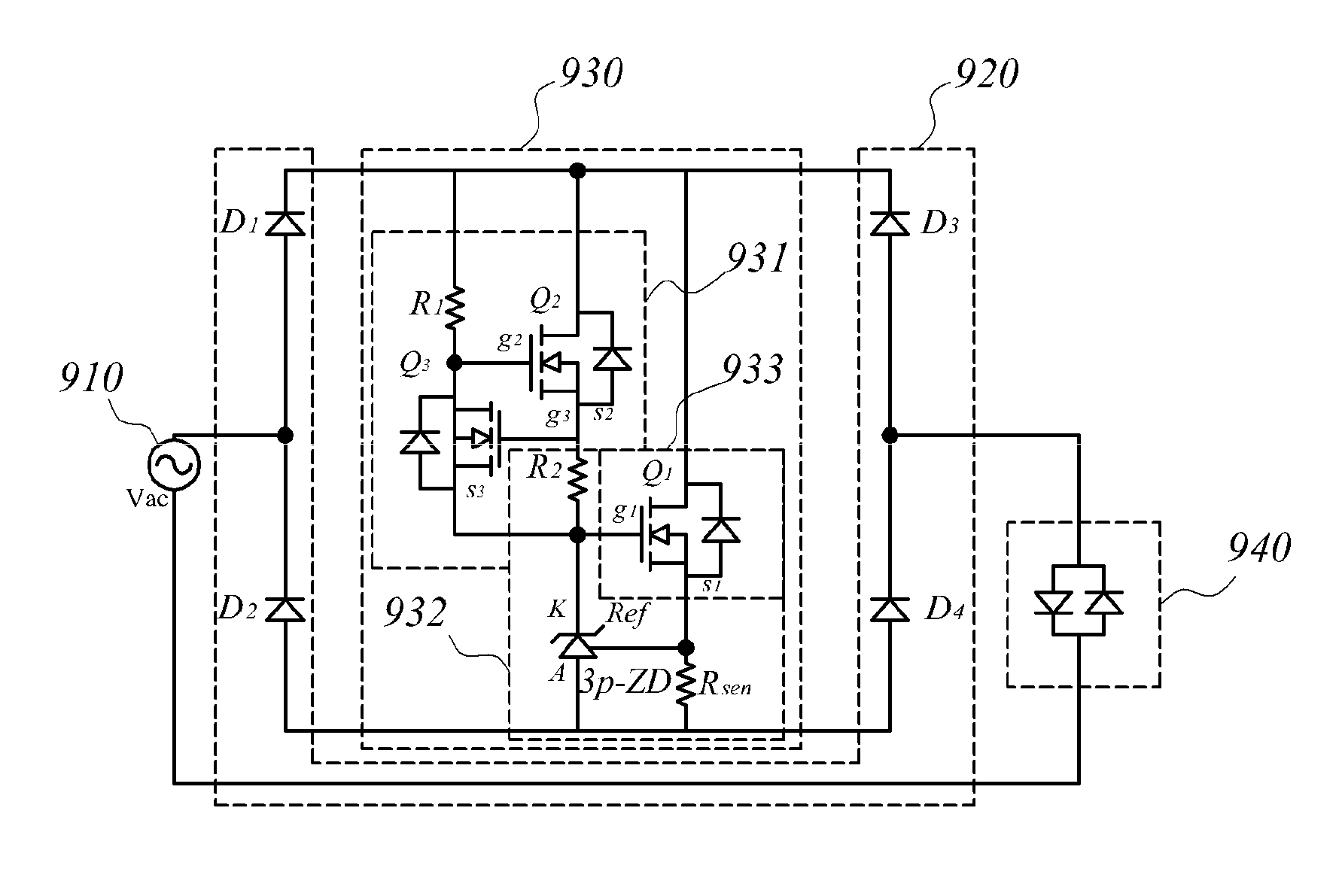
[0071]FIG. 10 is a circuit diagram of a constant-current-drive bidirectional LED module device in accordance with the present invention.

[0072]The constant-current-drive bidirectional LED module device in accordance with the embodiment of the present invention includes a rectifier 820 receiving and rectifying a commercial AC power source 810; a constant current unit 830 connected between lead legs D1 and D2 and lag legs D3 and D4 of the rectifying unit 820 to provide the constant current, and a bidirectional LED module unit 840 connected between the other end of the rectifying unit 820 and the other end 810 of the commercial AC power source 810.

[0073]The constant current unit 830 in accordance with the embodiment of the present invention includes a switching unit 831 connected between the lead legs D1 and D2 of the rectifying unit 820 and the lag legs D3 and D4 of the rectifying unit 820 and is switched by using the pulsating current output from the rectifier 820, a control voltage o...


PUM


Abstract

A constant-current-drive LED module device includes a rectifier configured to receive and rectify an alternating current power source; a unidirectional LED module unit configured to connect to one end of the rectifier; and a constant current unit configured to connect between the unidirectional LED module unit and the other end of the rectifier to control constant current.

Description

BACKGROUND OF THE INVENTION[0001]Exemplary embodiments of the present invention relate to a constant-current-drive LED module device, and more particularly, to an LED module device driven with constant current.[0002]A luminescent diode (LED) may be operated only when constant current is stably supplied to a current drive element. In particular, as the LED demanding high power requires large drive current (generally, 350 mA or more), the LED generates a significant amount of heat and as a result, has degradation in luminance larger than the LED driven with low power.[0003]This is directly connected with a lifespan of the LED and acts as very important factors in a lighting market. Therefore, all the LEDs driven with high power are driven with constant current and are driven by a pulse width modulation (PWM) scheme so as to more efficiently use power of an SMPS that is used as a constant-current power source.[0004]However, the PWM scheme requires electronic components, which leads to ...

Claims


Application Information

Patent Timeline
IPC IPC(8): H05B37/02H05B44/00
CPCH05B33/0818H05B45/395Y02B20/30H05B45/37
Inventor JUNG, HYE MANHA, SEOK JINPARK, IN KIKOO, SANG SHINKIM, JONG HYUN
Owner AIRTEC SYST CO LTD
Why Eureka
Try Eureka