Chassis-excited antenna apparatus and methods

Active Publication Date: 2012-08-16
CANTOR FITZGERALD SECURITIES
View PDF9 Cites 157 Cited by
  • Summary
  • Abstract
  • Description
  • Claims
  • Application Information

AI Technical Summary

Benefits of technology

[0047]FIG. 4 is a plot of measured total efficiency for the exemplary lower-band and

Problems solved by technology

The use of metal enclosures/chassis and smaller thickness of the device enclosure create new challenges for radio frequency (RF) antenna implementations.
These antenna solutions are often inadequate for the aforementioned thin devices with metal housings and/or chassis, as the vertical distance required to separate the radiator from the ground plane is no longer available.
Additionally, the metal body of the mobile device acts as an RF shield and degrades antenn

Method used


Image

  • Chassis-excited antenna apparatus and methods
  • Chassis-excited antenna apparatus and methods
  • Chassis-excited antenna apparatus and methods

Examples


exemplary embodiment 120

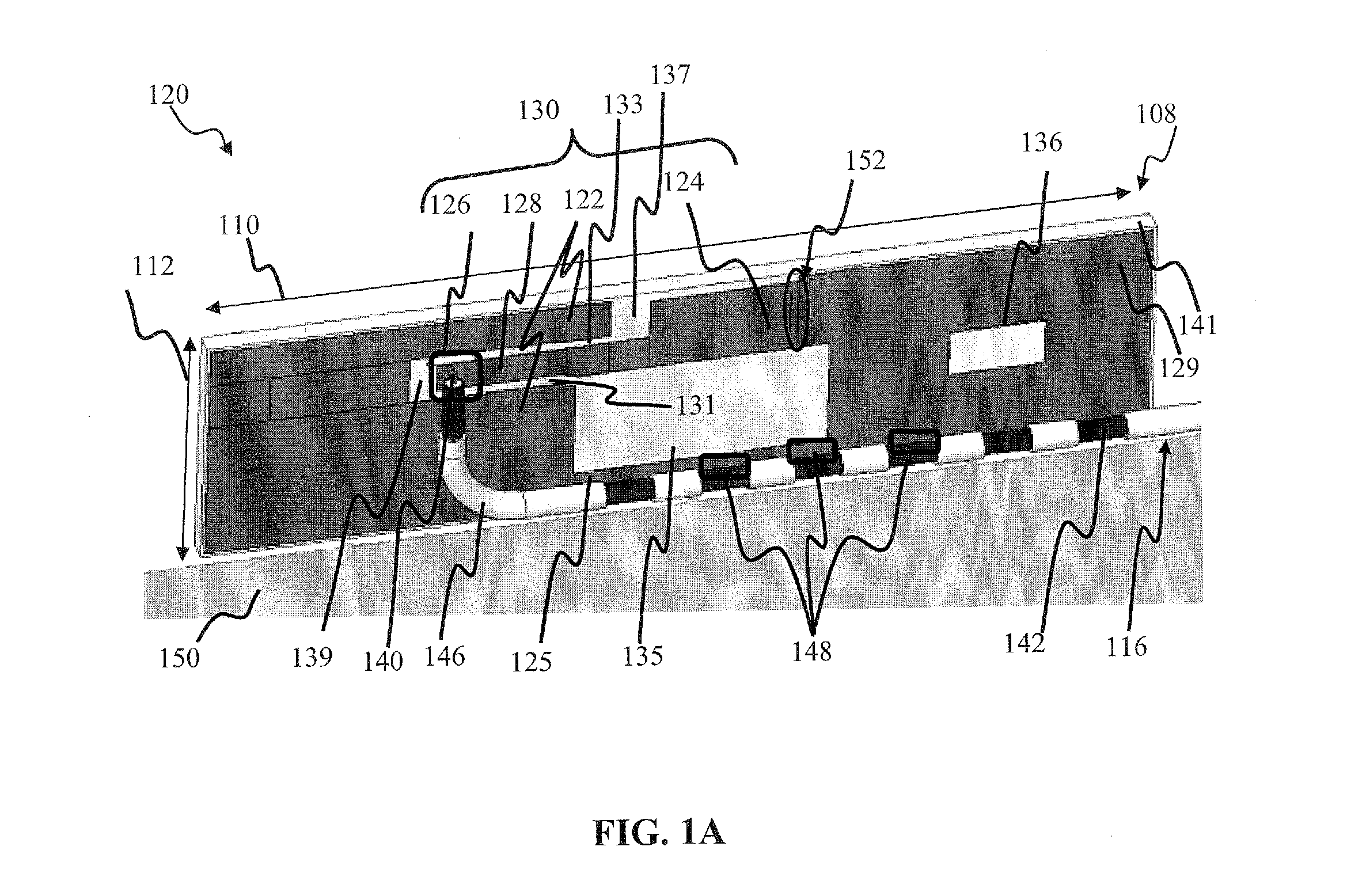
[0076]The detailed structure of an exemplary embodiment 120 of radiator element 108 configured for mounting in a radio device is presented in FIG. 1A. The radiator element 108 comprises a conductive coating 129 disposed on a rigid substrate 141, such as a PCB fabricated from a dielectric material (e.g., FR-4). Other suitable materials, such as glass, ceramic, air are useable as well. In one variant, a conductive layer is disposed on the opposing surface of the substrate, thereby forming a portion of a ground plane. In another implementation, the radiator element is fabricated as a flex circuit (either a single-sided, or double-sided) that is mounted on a rigid support element.

[0077]The conductive coating 129 is shaped to form a radiator structure 130, which includes a first portion 122 and a second portion 124, and is coupled to the feed conductor 116 at a feed point 126. The second portion 124 is coupled to the feed point 126 via a conductive element 128, which acts as a transmissi...

exemplary embodiment 200

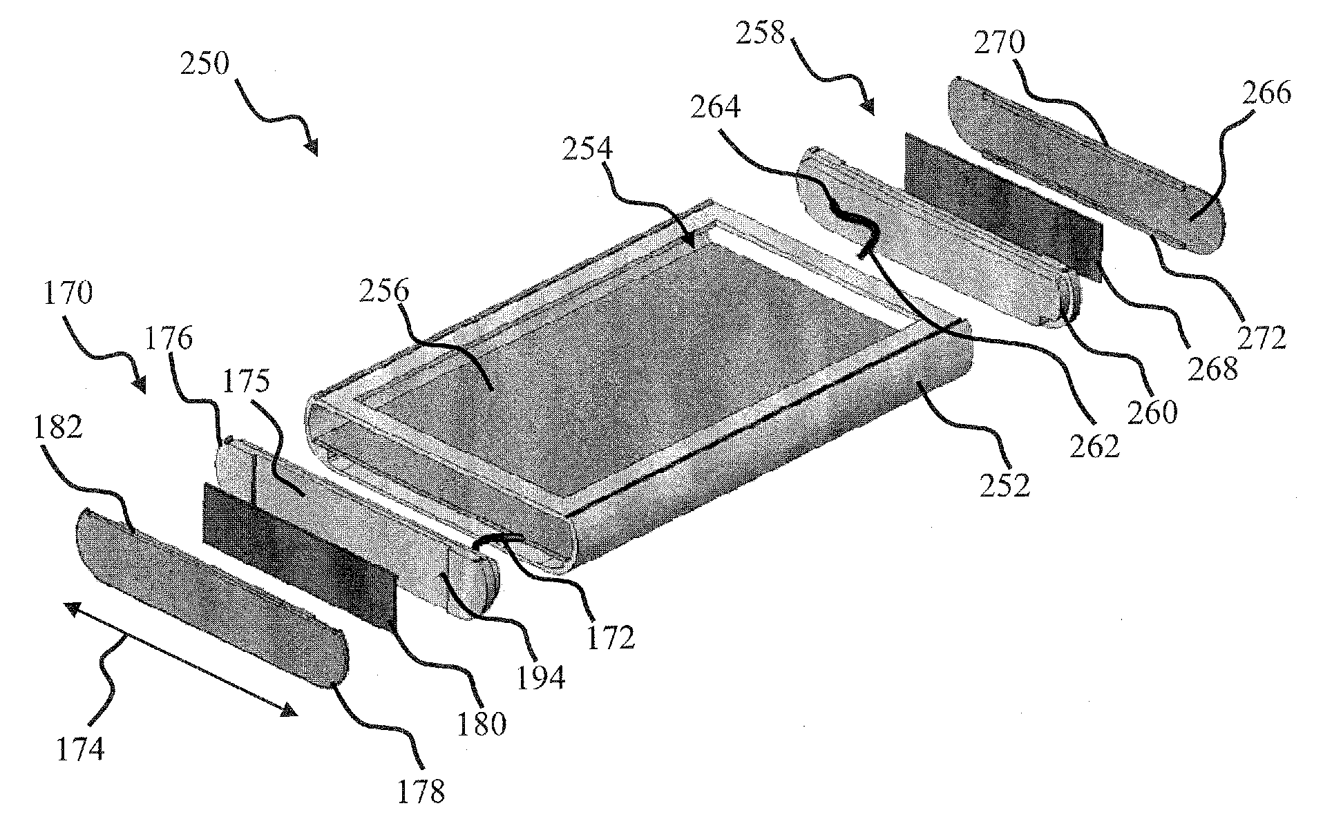
[0112]Referring now to FIG. 2A, an exemplary embodiment 200 of a mobile device comprising two antenna components configured in accordance with the principles of the present invention is shown and described. The mobile device comprises a metal enclosure (or chassis) 202 having a width 204, a length 212, and a thickness (height) 211. Two antenna elements 210, 230, configured similarly to the embodiment of FIG. 1A, are disposed onto two opposing sides 106, 206 of the housing 202, respectively. Each antenna element is configured to operate in a separate frequency band (e.g., one antenna 210 in a lower frequency band, and one antenna 230 in an upper frequency band, although it will be appreciated that less or more and / or different bands may be formed based on varying configurations and / or numbers of antenna elements). Other configurations may be used consistent with the present invention, and will be recognized by those of ordinary skill given the present disclosure. For example, both an...


PUM


Abstract

A chassis-excited antenna apparatus, and methods of tuning and utilizing the same. In one embodiment, a distributed loop antenna configuration is used within a handheld mobile device (e.g., cellular telephone). The antenna comprises two radiating elements: one configured to operate in a high-frequency band, and the other in a low-frequency band. The two antenna elements are disposed on different side surfaces of the metal chassis of the portable device; e.g., on the opposing sides of the device enclosure. Each antenna component comprises a radiator and an insulating cover. The radiator is coupled to a device feed via a feed conductor and a ground point. A portion of the feed conductor is disposed with the radiator to facilitate forming of the coupled loop resonator structure.

Description

COPYRIGHT[0001]A portion of the disclosure of this patent document contains material that is subject to copyright protection. The copyright owner has no objection to the facsimile reproduction by anyone of the patent document or the patent disclosure, as it appears in the Patent and Trademark Office patent files or records, but otherwise reserves all copyright rights whatsoever.[0002]1. Field of the Invention[0003]The present invention relates generally to antenna apparatus for use in electronic devices such as wireless or portable radio devices, and more particularly in one exemplary aspect to a chassis-excited antenna, and methods of tuning and utilizing the same.[0004]2. Description of Related Technology[0005]Internal antennas are commonly found in most modern radio devices, such as mobile computers, mobile phones, Blackberry® devices, smartphones, personal digital assistants (PDAs), or other personal communication devices (PCD). Typically, these antennas comprise a planar radiat...

Claims


Application Information

Patent Timeline
IPC IPC(8): H01Q1/24H01Q1/42H01Q7/00H01Q1/38H01Q1/50
CPCH01Q1/24H01Q1/38H01Q1/42H01Q1/50H01Q1/22H01Q1/243H01Q9/42H01Q13/10H01Q21/28H01Q7/00
Inventor RAMACHANDRAN, PRASADHANNAMAA, PETTERI
Owner CANTOR FITZGERALD SECURITIES
Why Eureka
Try Eureka