
Antenna seal assembly and method of making the same

Active Publication Date: 2012-08-16
AMPHENOL THERMOMETRICS
View PDF3 Cites 0 Cited by
  • Summary
  • Abstract
  • Description
  • Claims
  • Application Information

AI Technical Summary

Benefits of technology

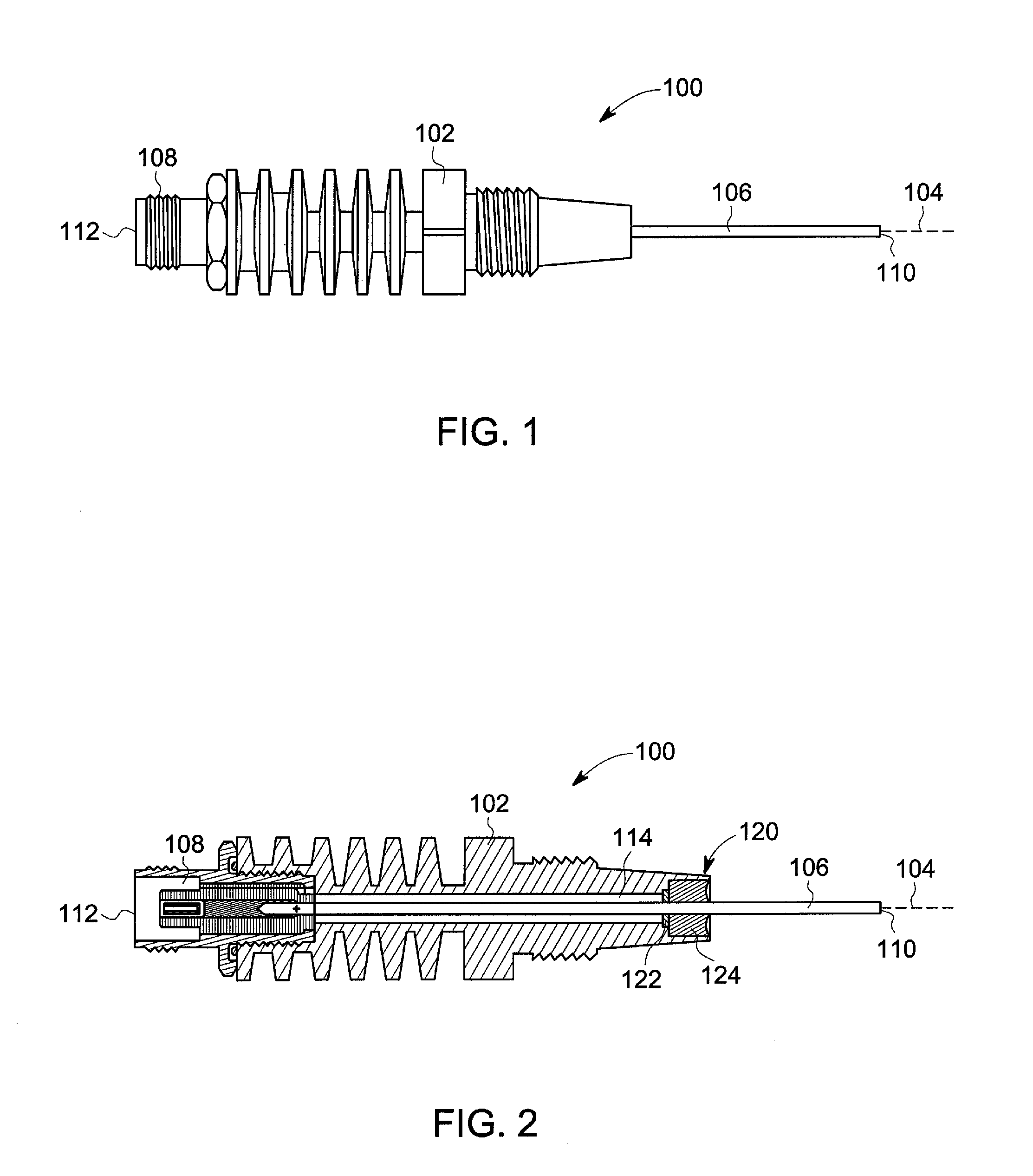
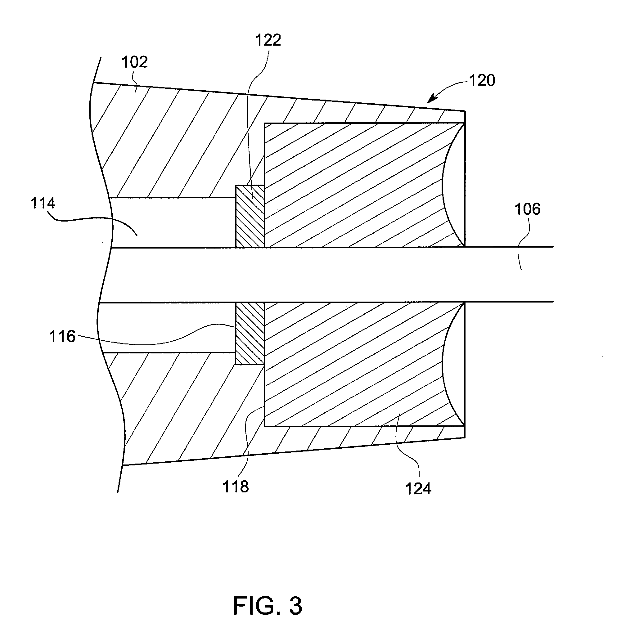
[0008]An antenna is disclosed, wherein the antenna includes a seal assembly comprising a seal plate to prevent material used to form a seal around the conductor element from entering into the air gap of the antenna body. An advantage that may be realized in the practice of some disclosed embodiments of the antenna is reduced variability among antennas of the same construction and produced by the same manufacturing process.

Problems solved by technology

But based on differences that result from the manufacturing process, antennas of the same construction often have varying characteristic impedances.
In existing antenna manufacturing processes, the distance that the seal slumps into the air gap varies from antenna to antenna, which results in significant variability between antennas.
This calibration takes time and resources, and often requires specific equipment and technical knowledge that are not necessarily available or cost effective to provide on-site.
In addition, this variability in characteristic impedance can increase the amount of reflection of the signal caused by the impedance mismatch between the coaxial cable and the antenna.
Reflection can disrupt the RF signal conduction and reduce the sensitivity of the antenna.

Method used


Image

  • Antenna seal assembly and method of making the same
  • Antenna seal assembly and method of making the same
  • Antenna seal assembly and method of making the same

Examples


experimental examples

[0023]In view of the foregoing, it is further noted that antennas of the type disclosed and contemplated herein can be readily replaced in the DPF monitoring systems discussed previously because of the limited variability between such antennas. To exemplify this favorable level of variability, reference is had to the experimental data collected from experiments conducted in a DPF monitoring system. That is, an RF signal having a frequency swept between 700 mHz and 900 mHz was transmitted from a first antenna positioned on one side of a DPF and received at a second antenna on the other side of the DPF. The level of attenuation (in decibels) was measured, as between the transmitted RF signal and the received RF signal.

[0024]Table 1 below summarizes data collected from multiple separate antennas. In experiment 1, each of the antennas were constructed without the seal plate disclosed above, resulting in the seal entering into the air gap at different depths, producing different characte...


PUM

PropertyMeasurementUnit
Signal attenuationaaaaaaaaaa

Abstract

An antenna and method of making the same is disclosed wherein the antenna includes a seal assembly comprising a seal plate to prevent material used to form a seal around the conductor element from entering into the air gap of the antenna body.

Description

BACKGROUND OF THE INVENTION[0001]The subject matter disclosed herein relates to signal transmitting and receiving devices, and more particularly, to a seal assembly for an antenna and the method of making the same.[0002]Devices for transmitting or receiving signals, such as antennas, are used in many diverse applications, including applications where the attenuation level of a signal is measured as between two antennas. For example, the attenuation of a radio frequency (“RF”) signal can be used to monitor certain performance characteristics of filters, such as diesel particulate filters (“DPF”).[0003]A DPF is a device designed to trap and remove diesel particulate matter (i.e., soot) from the exhaust gas of diesel engines as the exhaust gas passes through the DPF in order to reduce emissions and improve efficiency. Since a DPF must periodically be cleaned when the soot loading of the DPF exceeds a certain threshold, a DPF monitoring system with DPF sensors can be employed to monitor...

Claims


Application Information

Patent Timeline
IPC IPC(8): H01Q1/14H01P11/00
CPCH01Q1/12H01Q9/30H01Q1/3291Y10T29/49016H01Q1/002
Inventor GEER, DAVID JOHN
Owner AMPHENOL THERMOMETRICS
Learn More