Shaft coupling mechanism

Inactive Publication Date: 2012-08-16
OILES CORP
View PDF9 Cites 16 Cited by
  • Summary
  • Abstract
  • Description
  • Claims
  • Application Information

AI Technical Summary

Benefits of technology

[0018]According to the present invention, it is possible to provide a shaft coupling mechanism which makes it possible to eliminate the occurrence of collision noise in the axial relative displacement of one rotating shaft relative to the other rotating shaft and does not generate unpleasant frictional noise in the transmission of the rotation of one rotating shaft to the other rotating shaft, and which makes it possible to sec

Problems solved by technology

In the case where the steering shaft and the rotating shaft are coupled by means of the shaft coupling mechanism, there is a possibility that an impact at the time of the reversing of the output rotating shaft of the electric motor and the vibration of the brushes of the electric motor are transmitted to the steering wheel through the shaft coupling mechanism and the steering shaft, thereby causing an unpleasant steering feel to the driver.
However, if the spacer is made softer by

Method used


Image

  • Shaft coupling mechanism
  • Shaft coupling mechanism
  • Shaft coupling mechanism

Examples


Embodiment Construction

[0022]Next, a more detailed description will be given of the mode of carrying out the invention on the basis of a preferred embodiment illustrated in the drawings. It should be noted that the present invention is not limited to this embodiment.

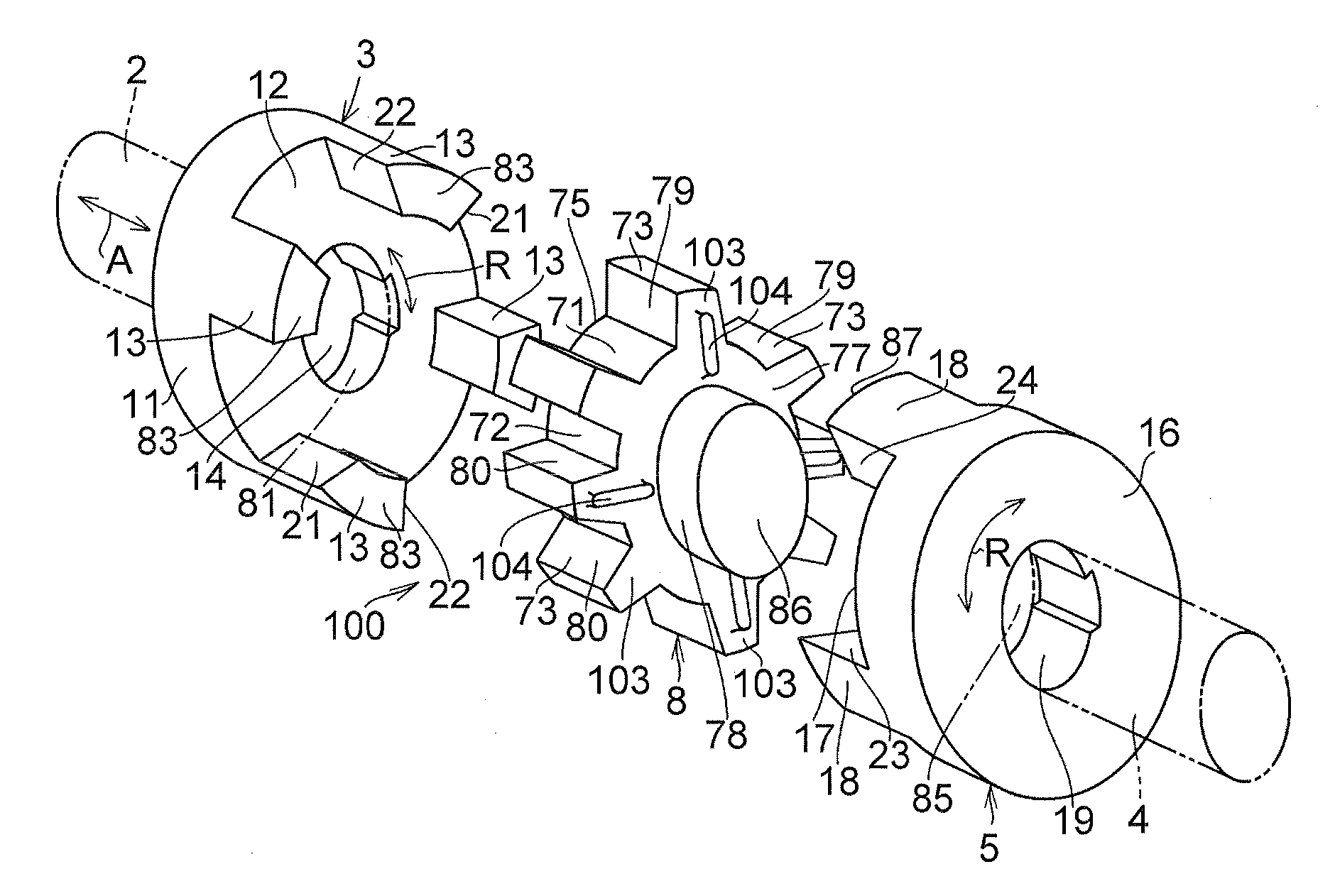
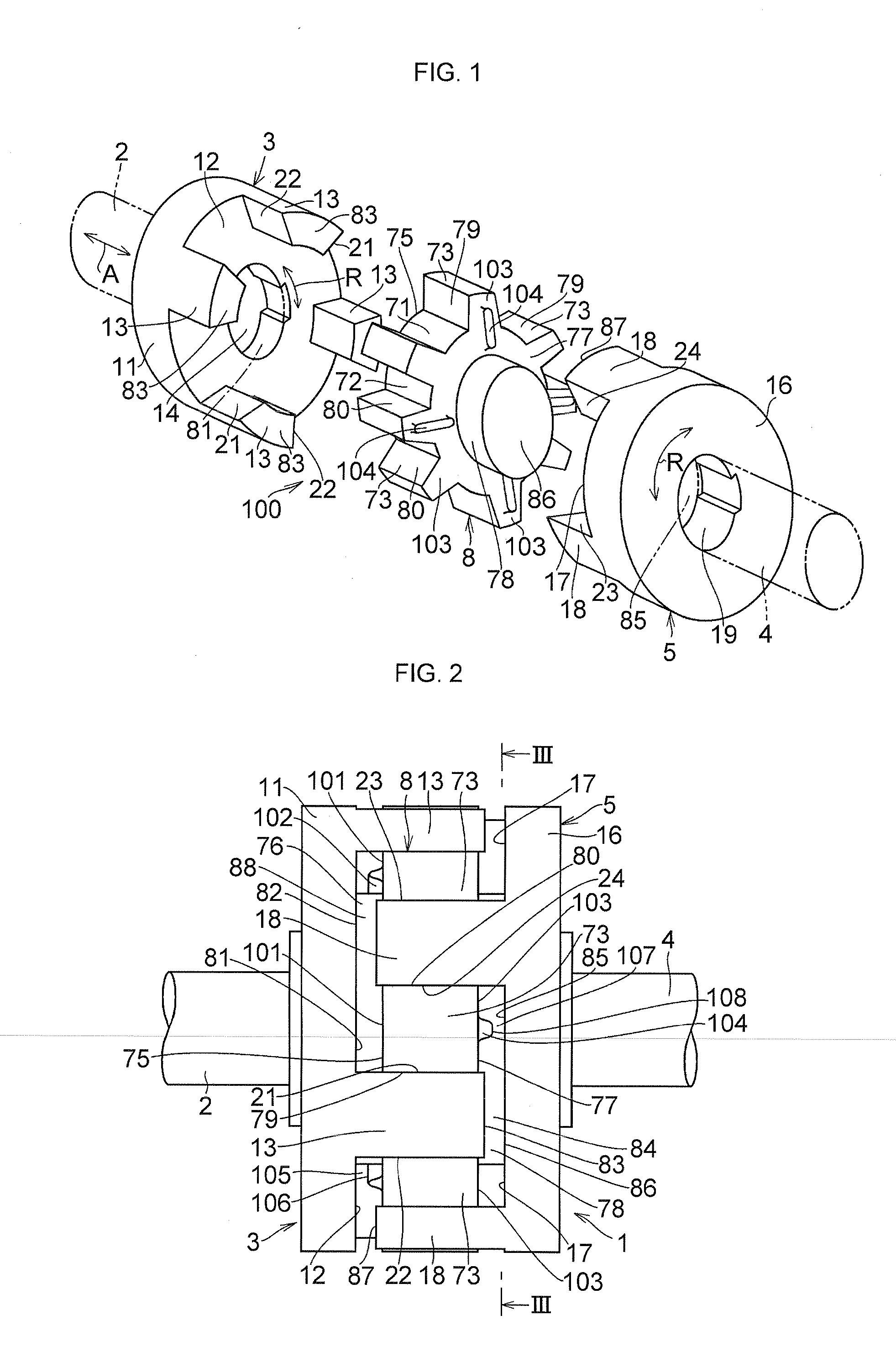
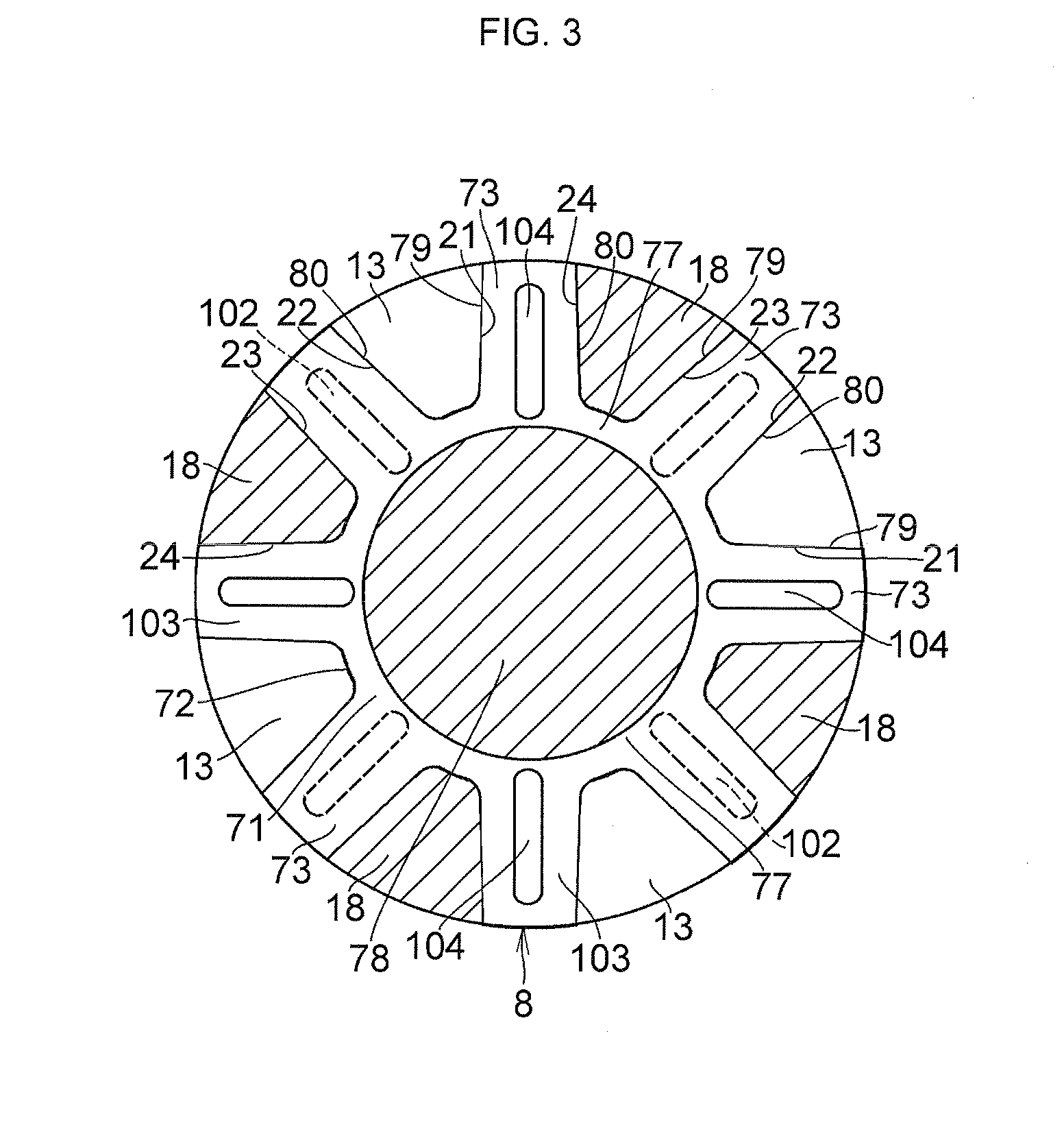
[0023]In FIGS. 1 to 3, a shaft coupling mechanism 1 for an electric power steering apparatus in accordance with this embodiment is comprised of a coupling base body 3 coupled to a rotating shaft 2 on an electric motor side of an electric power steering apparatus; a coupling base body 5 coupled to a steering shaft 4 serving as a rotating shaft; and an intermediate interposed member 8 interposed between both coupling base bodies 3 and 5 and adapted to transmit the rotation of the rotating shaft 2 in an R direction to the steering shaft 4 in cooperation with both coupling base bodies 3 and 5.

[0024]The coupling base body 3 which is rigid includes an annular base portion 11; two pairs of axial projecting portions 13 which project integrally from on...


PUM


Abstract

A shaft coupling mechanism 1 for an electric power steering apparatus includes a coupling base body 3 coupled to a rotating shaft 2 on an electric motor side of an electric power steering apparatus; a coupling base body 5 coupled to a steering shaft 4 serving as a rotating shaft; and an intermediate interposed member 8 interposed between both coupling base bodies 3 and 5 and adapted to transmit the rotation of the rotating shaft 2 in an R direction to the steering shaft 4 in cooperation with both coupling base bodies 3 and 5.

Description

TECHNICAL FIELD[0001]The present invention relates to a shaft coupling mechanism suitable for coupling a rotating shaft on a rotating source side such as an electric motor in an electric power steering apparatus and a rotating shaft on an operating side such as a steering shaft of an automobile.BACKGROUND ART[0002]An electric power steering apparatus, for example, is for facilitating the manual steering of a steering wheel by adding a torque based on the rotation of an output rotating shaft of an electric motor to a torque based on the rotation of the steering wheel which is manually operated. In such an electric power steering apparatus, the steering shaft on the steering wheel side and the rotating shaft on the output rotating shaft side of the electric motor are coupled by means of a shaft coupling mechanism (a coupling).[0003]In the case where the steering shaft and the rotating shaft are coupled by means of the shaft coupling mechanism, there is a possibility that an impact at ...

Claims


Application Information

Patent Timeline
IPC IPC(8): F16D3/68F16D3/12
CPCF16D3/68B62D5/04F16D3/12
Inventor NAKAGAWA, NOBORUYOSHIMOTO, DAISUKE
Owner OILES CORP
Why Eureka
Try Eureka