Brake fluid pressure control apparatus for vehicle

a control apparatus and brake fluid technology, applied in the direction of braking systems, instruments, analogue processes for specific applications, etc., can solve the problems of insufficient rollover prevention control, the vehicle is liable to roll, so as to improve the rollover prevention control, reduce the speed of the vehicle, and avoid unnecessary braking force

Active Publication Date: 2012-08-23
HONDA MOTOR CO LTD +1
View PDF24 Cites 15 Cited by
  • Summary
  • Abstract
  • Description
  • Claims
  • Application Information

AI Technical Summary

Benefits of technology

[0050]With this configuration of the brake fluid pressure control apparatus, since braking forces are applied to front and rear wheels, the vehicle speed can be reduced promptly to improve the rollove...

Problems solved by technology

A vehicle is liable to roll over due to counteraction of roll, particularly when the driver steers back the steering wheel of a vehicle which is turning in one direction to the opposite direction so as to cause the vehicle to turn in the opposite direction.
However, measuring physical quantities such as a lateral acceleration and a roll angle, which are equivalent to the actual roll angle of the vehicle, and then determining whether or not the vehicle is likely to roll over based on the measurement result may disadvantageously result in a drawback that the rollover prevention control will not sufficiently act on the vehicle if a rollover tendency of the vehicle increases more abruptly than normal.
For example, if the driver of the vehicle executes an abrupt steering maneuver or a steering-back maneuver while the vehicle is turning, the vehicle is liable to roll over due to rolling-back...

Method used


Image

  • Brake fluid pressure control apparatus for vehicle
  • Brake fluid pressure control apparatus for vehicle
  • Brake fluid pressure control apparatus for vehicle

Examples


Embodiment Construction

[0075]With reference to the attached drawings, a preferred embodiment of the present invention will be described.

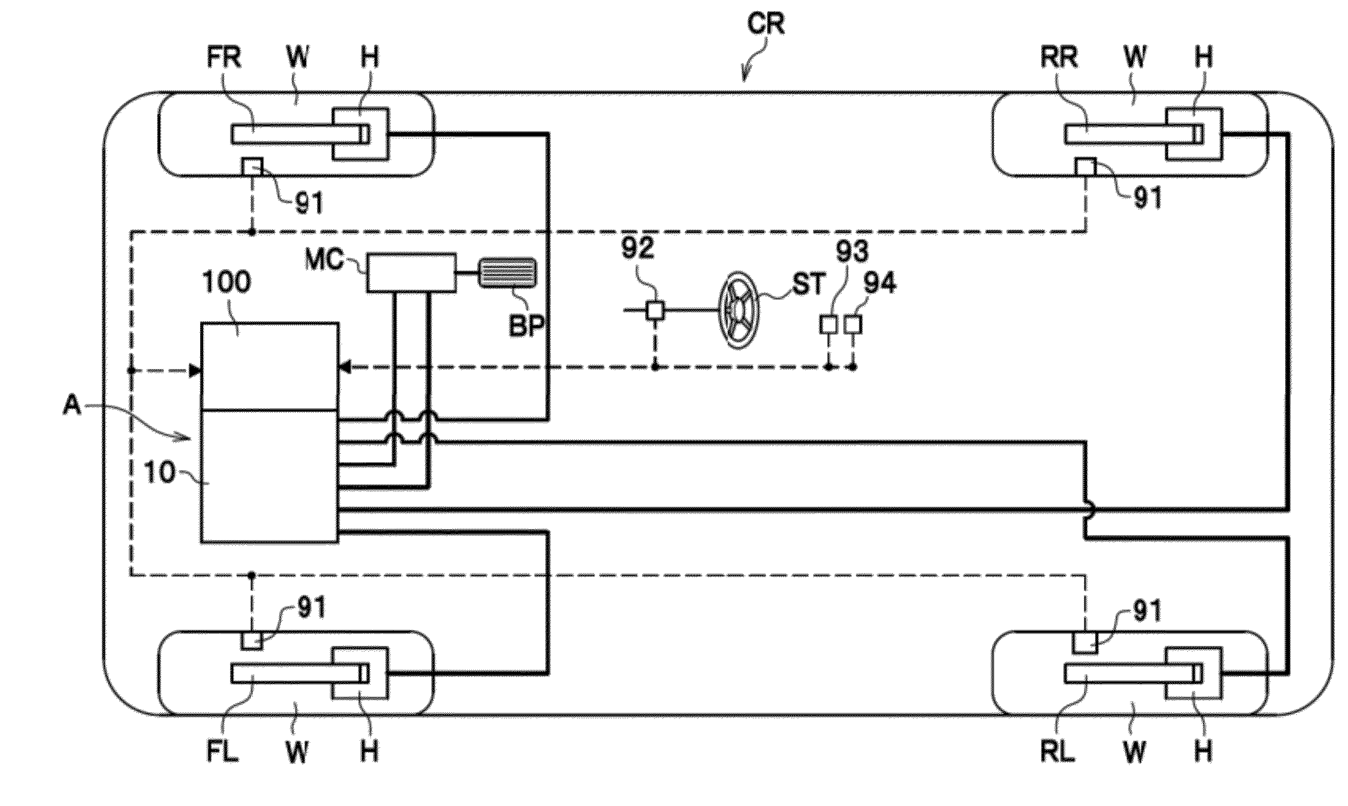
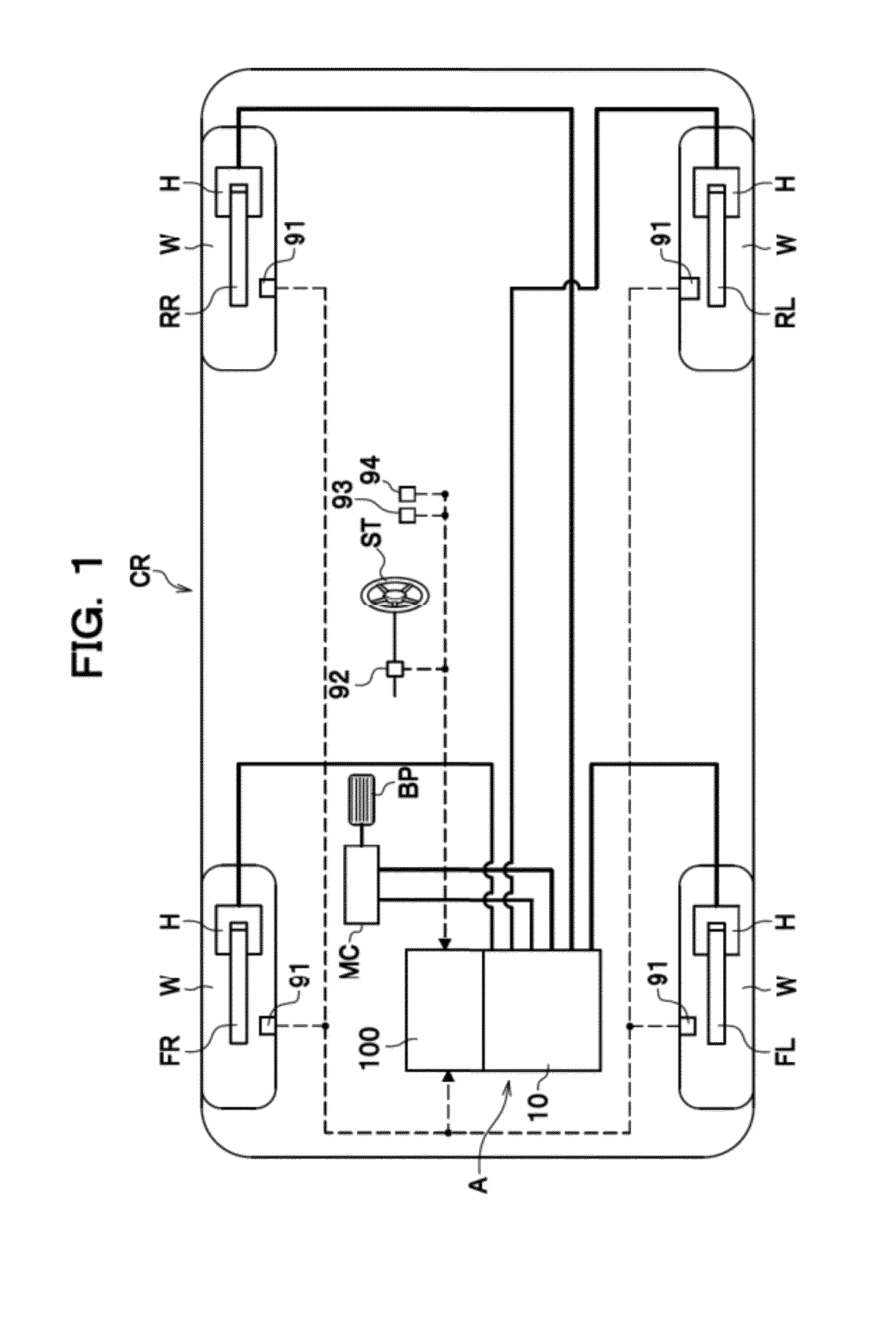
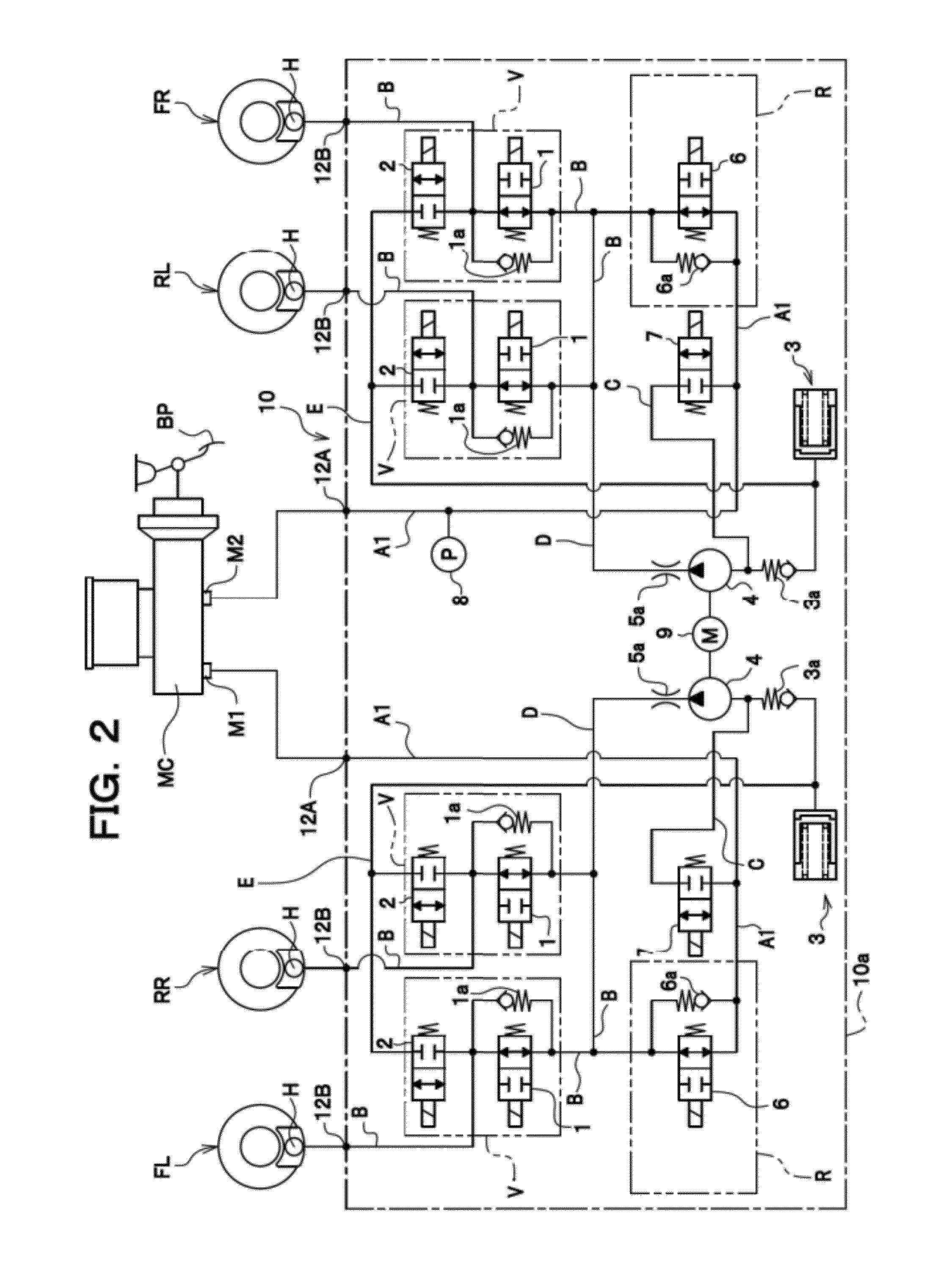
[0076]As seen in FIG. 1, a brake fluid pressure control apparatus A for a vehicle CR controls a braking force (brake fluid pressure) applied to each wheel W of the vehicle CR where appropriate. The brake fluid pressure control apparatus A comprises a fluid pressure unit 10 in which brake fluid passages (fluid pressure passages) and various parts are provided, and a controller 100 for appropriately controlling the various parts within the fluid pressure unit 10.

[0077]Connected to the controller 100 of the brake fluid pressure control apparatus A are wheel speed sensors 91 each for detecting wheel speed of a wheel W, a steering angle sensor 92 for detecting steering angle of a steering wheel ST, a lateral acceleration sensor 93 for detecting acceleration acting in a lateral direction of the vehicle CR (i.e., lateral acceleration), and a yaw rate sensor 94 for detecting turn...


PUM


Abstract

A brake fluid pressure control apparatus for a vehicle includes a parameter calculation unit configured to calculate a rollover detection parameter; and a steering maneuver determination unit configured to determine whether an abrupt steering maneuver is made. The parameter calculation unit is configured to calculate a first composition roll angle as the rollover detection parameter, by combining at a predetermined weight assignment ratio a first roll angle equivalent to an actual roll angle with a second roll angle obtained using a parameter which changes with a phase earlier than the first roll angle, and to calculate the first composition roll angle by changing the weight assignment ratio such that a weight of the second roll angle is higher when the steering maneuver determination unit determines that an abrupt steering maneuver is made than when the steering maneuver determination unit determines that the abrupt steering maneuver is not made.

Description

CROSS REFERENCE TO RELATED APPLICATIONS[0001]This application claims the foreign priority benefit under Title 35, United States Code, §119(a)-(d) of Japanese Patent Application Nos. 2011-036439, 2011-036110, and 2011-036441 filed on Feb. 22, 2011 in the Japan Patent Office, the disclosures of which are herein incorporated by reference in its entirety.BACKGROUND OF THE INVENTION[0002]The present invention relates to a brake fluid pressure control apparatus for a vehicle, and more particularly to a brake fluid pressure control apparatus for a vehicle, which controls brake to prevent rollover of the vehicle.[0003]As disclosed in JP2001-509448A (hereinafter referred to as Patent Literature 1), there is known a technique for preventing rollover of a vehicle by applying a braking force to at least one wheel to stabilize the vehicle when a driver steers the vehicle into a sharp turn and the vehicle is about to roll over.[0004]As disclosed in JP10-081215A (hereinafter referred to as Patent ...

Claims


Application Information

Patent Timeline
IPC IPC(8): B60T13/66B60T8/1755G06F19/00
CPCB60T7/042B60T8/17554B60T2230/03B60T13/686B60T13/662
Inventor MIYATA, KAZUAKIKOJIMA, TAKESHIFUTAMURA, TOMOYUKI
Owner HONDA MOTOR CO LTD
Why Eureka
Try Eureka