
Object Tracking for Artificial Vision

a technology of artificial vision and object tracking, applied in the field of object tracking for artificial vision, can solve the problems of blind spot in the centre of the field and leave the peripheral vision inta

Active Publication Date: 2012-08-23
NAT ICT AUSTRALIA
View PDF14 Cites 42 Cited by
  • Summary
  • Abstract
  • Description
  • Claims
  • Application Information

AI Technical Summary

Benefits of technology

[0010]The apparatus may permit the user to select one or more objects to be displayed in respective reserved areas of the displayed images. This allows the user to select which people's faces are displayed in which part of their field of vision. It may alternatively allow the user to switch between the face detected faces, for instance when the user speaking to different people.

Problems solved by technology

However, many common forms of blindness results from damage to the retina, for instance macular degeneration leads to deterioration in the cells of the fovea, causing a blind spot in the centre of the field of vision; but leaving the peripheral vision intact.

Method used


Image

  • Object Tracking for Artificial Vision
  • Object Tracking for Artificial Vision

Examples


Embodiment Construction

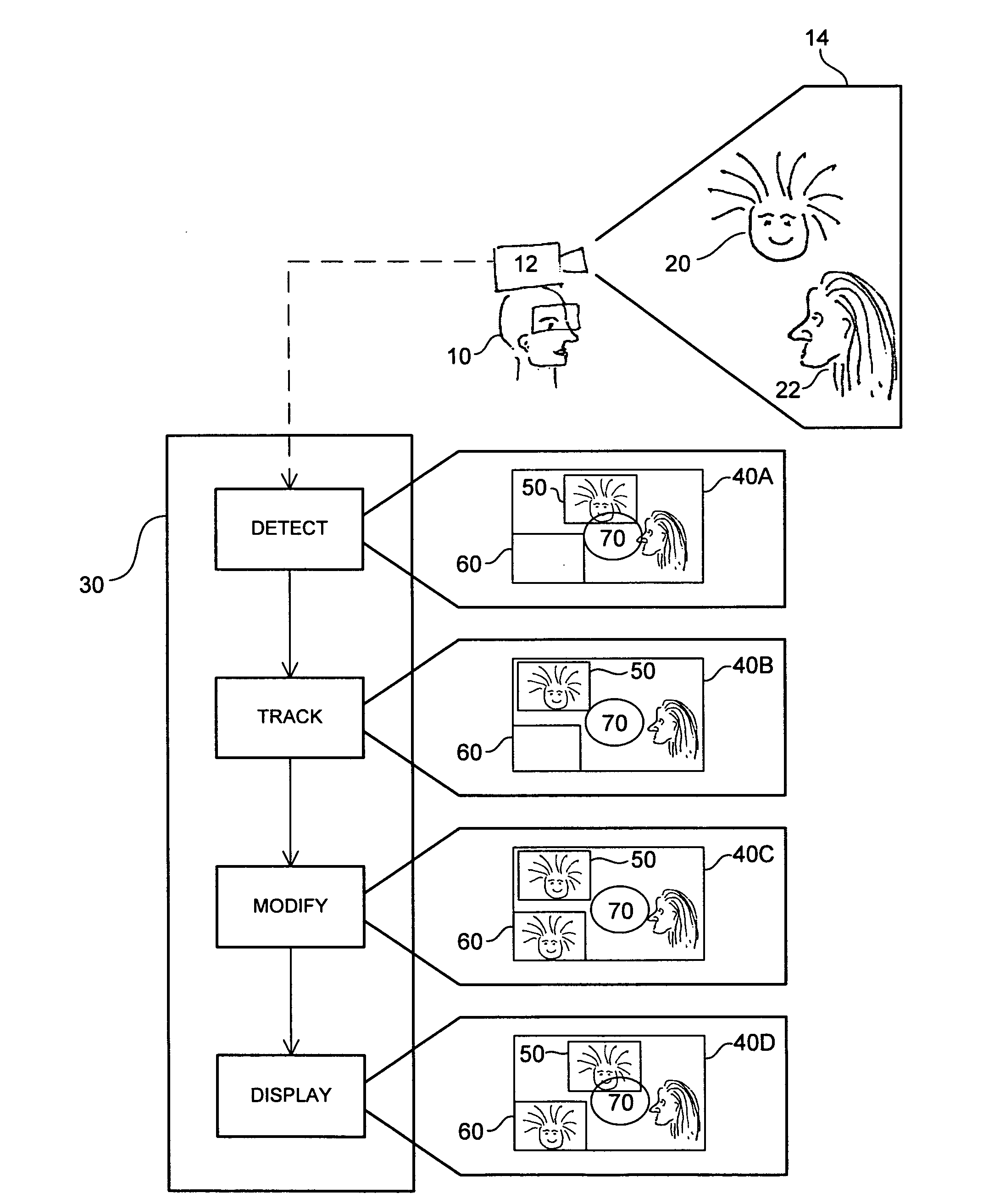
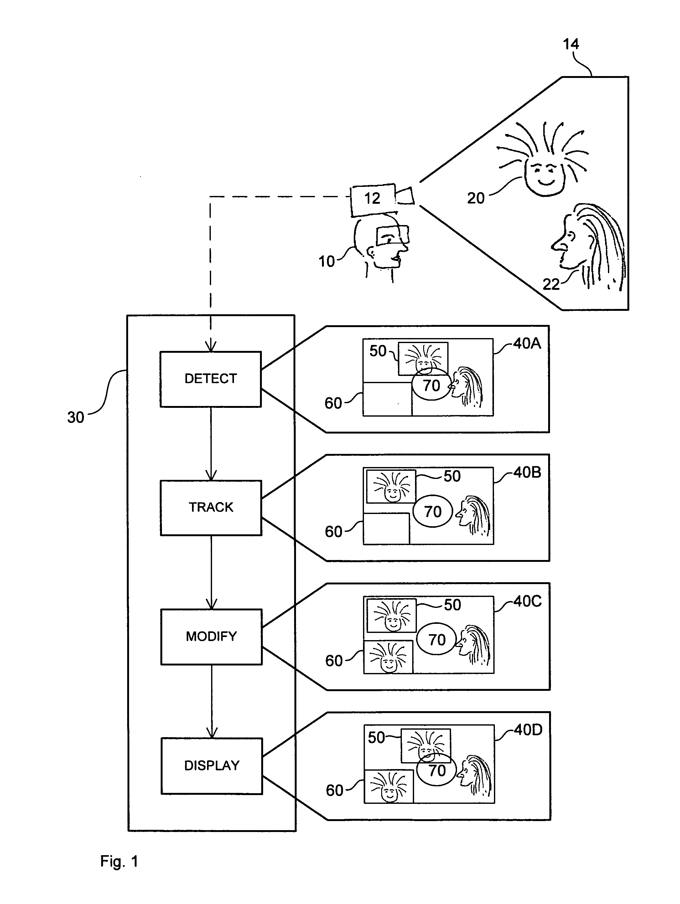
[0020]The visually impaired user 10 wears an inconspicuous high resolution camera 12 and a pair of vision spectacles that provide a stereoscopic image of the scene 14 in front of the camera. Since the camera is worn by the user their movements cause the scene in front of the camera to change. In the scene shown there are two other people 20 and 22; friends of the user. As the three converse the user may move their head to face each of the friends 20 and 22 as they talk. Each of the three may also move around in the scene as they wish.

[0021]The camera 12 records the scene in front of it, and a processor 30 in the camera processes the recorded video data in real time. In FIG. 1 a single monoscopic image is shown being processed at four different instances of time, 40A, 40B, 40C and 40D.

[0022]The first thing the processor 30 does is to detect the face of user 20; at time 40A. Face detection algorithms work in different ways and this one uses a pre-trained model using statistical machin...


PUM


Abstract

This invention concerns the tracking of objects in video data for artificial vision; for instance for a bionic eye. More particularly, the invention concerns a vision enhancement apparatus for a vision-impaired user. In other aspects, the invention concerns a method for enhancing vision and software to perform the method. The image processor operates to process video data representing images of a scene. Automatically detect and track a user selected object, such as a face, in the images. And, automatically modify the video data, by reserving a user selected area of the displayed images for displaying the tracked object as a separate video tile within the scene. The separate video tile remains in the selected area despite movement of the camera relative to the scene, or movement of the user relative to the object or the scene.

Description

TECHNICAL FIELD[0001]This invention concerns the tracking of objects in video data for artificial vision; for instance for a bionic eye. More particularly, the invention concerns a vision enhancement apparatus for a vision-impaired user. In other aspects, the invention concerns a method for enhancing vision and software to perform the method.BACKGROUND ART[0002]Following the enormous success achieved by bionic ears in returning hearing to profoundly deaf people, interest has now turned to developing a bionic eye that will return sight to the blind.[0003]The eye operates by focusing light onto the retina which in turn passes signals to the brain, via the optic nerve, where they are processed to provide sight. Partial or total blindness can be caused by damage or malfunction of any of the elements in the chain from eye to brain. However, many common forms of blindness results from damage to the retina, for instance macular degeneration leads to deterioration in the cells of the fovea,...

Claims


Application Information

Patent Timeline
Patent Type & Authority Applications(United States)
IPC IPC(8): H04N7/18G06V10/20
CPCA61F9/08A61N1/36046H04N7/002G06T11/60G09B21/008G06K9/605G06V10/20
Inventor BARNES, NICKSHEN, CHUNHUA
Owner NAT ICT AUSTRALIA
Learn More