
System and method of controlling vision device for tracking target based on motion commands

Active Publication Date: 2012-08-23
SEOUL NAT UNIV R&DB FOUND
View PDF19 Cites 12 Cited by
  • Summary
  • Abstract
  • Description
  • Claims
  • Application Information

AI Technical Summary

Benefits of technology

[0010]By adopting the system and the method of controlling the vision device based on motion commands according to an aspect, the motion information of the locomobile robot may be recognized by using a motion command for driving the locomobile robot or using a detection result obtained from various sensors in addition to the motion command. Then, the motion of the vision device is controlled so that the line of sight of the vision device of the locomobile robot is fixed to the target on the basis of the obtained motion information. As a result, the direction of the line of sight of the vision device may be maintained to be constantly directed to the recognition target even when the locomobile robot continuously moves linearly and / or rotates. That is, the recognition target may be made to be continuously positioned at the center of the output image frame of the vision device.
[0011]Accordingly, since the vision device watches the recognition target even when the locomobile robot continuously moves for a long period of time, a deviation of the target from the recognition range of the vision device may be prevented, and a phenomenon such as blurring may be prevented from occurring in an image even when the target is not deviated from the recognition range. Accordingly, reliable image information may be obtained even when the locomobile robot moves, so that the recognition rate and the tracking success rate of the vision device may improve. Further, motion information estimated from motion commands is compared with motion information actually detected from various sensors, and thus, disturbance such as slip or collision which may be generated in travelling may be detected and an error caused by disturbance may be corrected.

Problems solved by technology

However, since the traveling unit and the vision system of the locomobile robot are connected to the same body, there is a problem in that a target to be recognized by the vision system is deviated from the input range of the vision system when the traveling unit of the robot rotates or the vision system installation portion rotates.
Furthermore, even when the target is not deviated from the input range, a phenomenon such as blurring occurs in image signals acquired by the vision system, which causes a problem in that an object recognition rate and an accuracy of the vision system is degraded.

Method used


Image

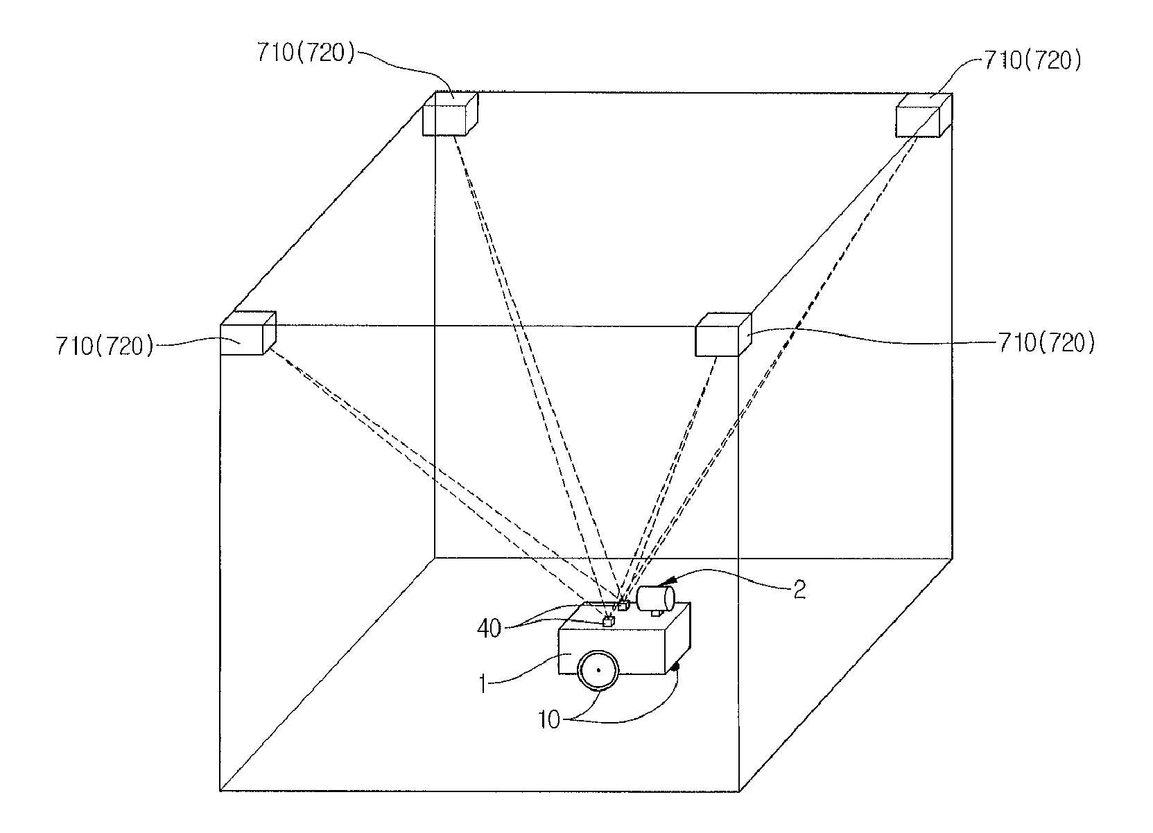
  • System and method of controlling vision device for tracking target based on motion commands
  • System and method of controlling vision device for tracking target based on motion commands
  • System and method of controlling vision device for tracking target based on motion commands

Examples


Embodiment Construction

[0019]Exemplary embodiments now will be described more fully hereinafter with reference to the accompanying drawings.

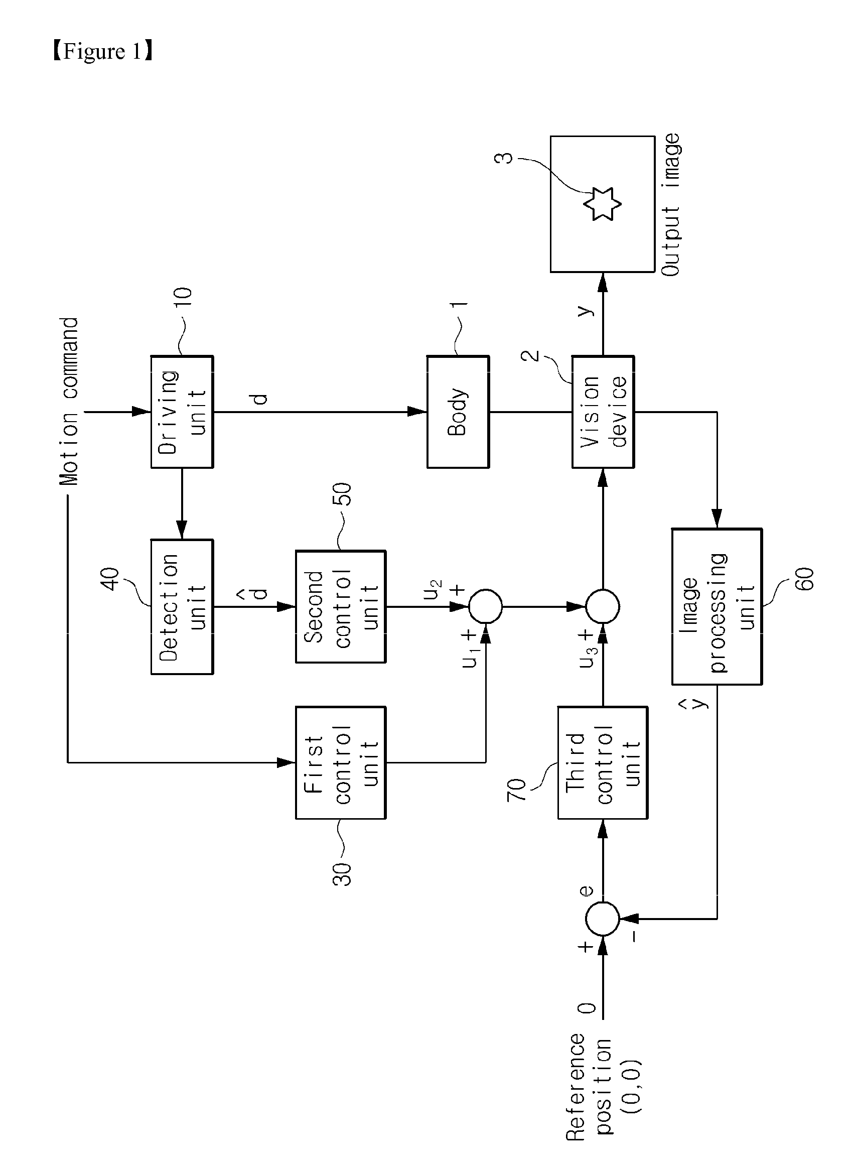
[0020]FIG. 1 is a block diagram illustrating a configuration of a system of controlling a vision device based on motion commands according to an embodiment.

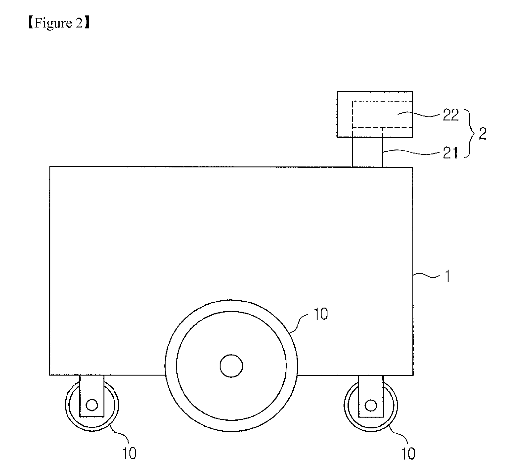
[0021]Referring to FIG. 1, a system of controlling a vision device based on motion commands may include a movable body 1, a vision device 2 connected to the body 1 and receiving image information, a driving unit 10 driving the body 1, and a first control unit 30 controlling the vision device 2 by a feedforward control. In an embodiment, the system of controlling the vision device based on motion commands may further include a detection unit 40 and a second control unit 50 which are used to detect disturbance generated in the body 1 and control the vision device 2 by a feedforward control. Furthermore, in an embodiment, the system of controlling the vision device based on motion commands may further include an image...


PUM


Abstract

A system of controlling a vision device based on motion commands may include: a movable body; a vision device driven by being connected to the body and receiving image information; a driving unit driving the body in accordance with a motion command; and a control unit which calculates motion information of the body using the motion command and drives the vision device so as to compensate an influence caused by the motion of the body using the calculated motion information. By using the system, reliable image information may be obtained in a manner such that a vision device included in a subject such as a locomobile robot is controlled to watch a predetermined target even when the subject moves.

Description

TECHNICAL FIELD[0001]The present disclosure relates to a system and a method of controlling a vision device for tracking a target based on motion commands. Specifically, the disclosure relates to a system and a method of controlling a vision device based on motion commands capable of controlling a motion of a vision device so that a line of sight of the vision device attached to a locomobile robot is fixed to a recognition target using motion commands or motion commands and motion information detected by the locomobile robot.BACKGROUND ART[0002]A locomobile robot has been widely used for carrying out tasks such as a monitoring security service. In order that the locomobile robot carries out such tasks, there is an essential demand for a function of moving the robot and changing the direction thereof using a traveling unit thereof. Furthermore, in the locomobile robot, it is one of core functions to implement a vision system that acquires external image signals so as to carry out a f...

Claims


Application Information

Patent Timeline
IPC IPC(8): H04N5/225
CPCG05D1/0246
Inventor CHO, DONG-ILPARK, JAEHONG
Owner SEOUL NAT UNIV R&DB FOUND
Learn More