Electronic device
a technology of electronic devices and electronic components, applied in the direction of color television details, television system details, television systems, etc., can solve the problems of poor composition, difficult to obtain a satisfactory processed image, and deviating from the desired composition of the shot imag
- Summary
- Abstract
- Description
- Claims
- Application Information
AI Technical Summary
Benefits of technology
Problems solved by technology
Method used
Image
Examples
example 1
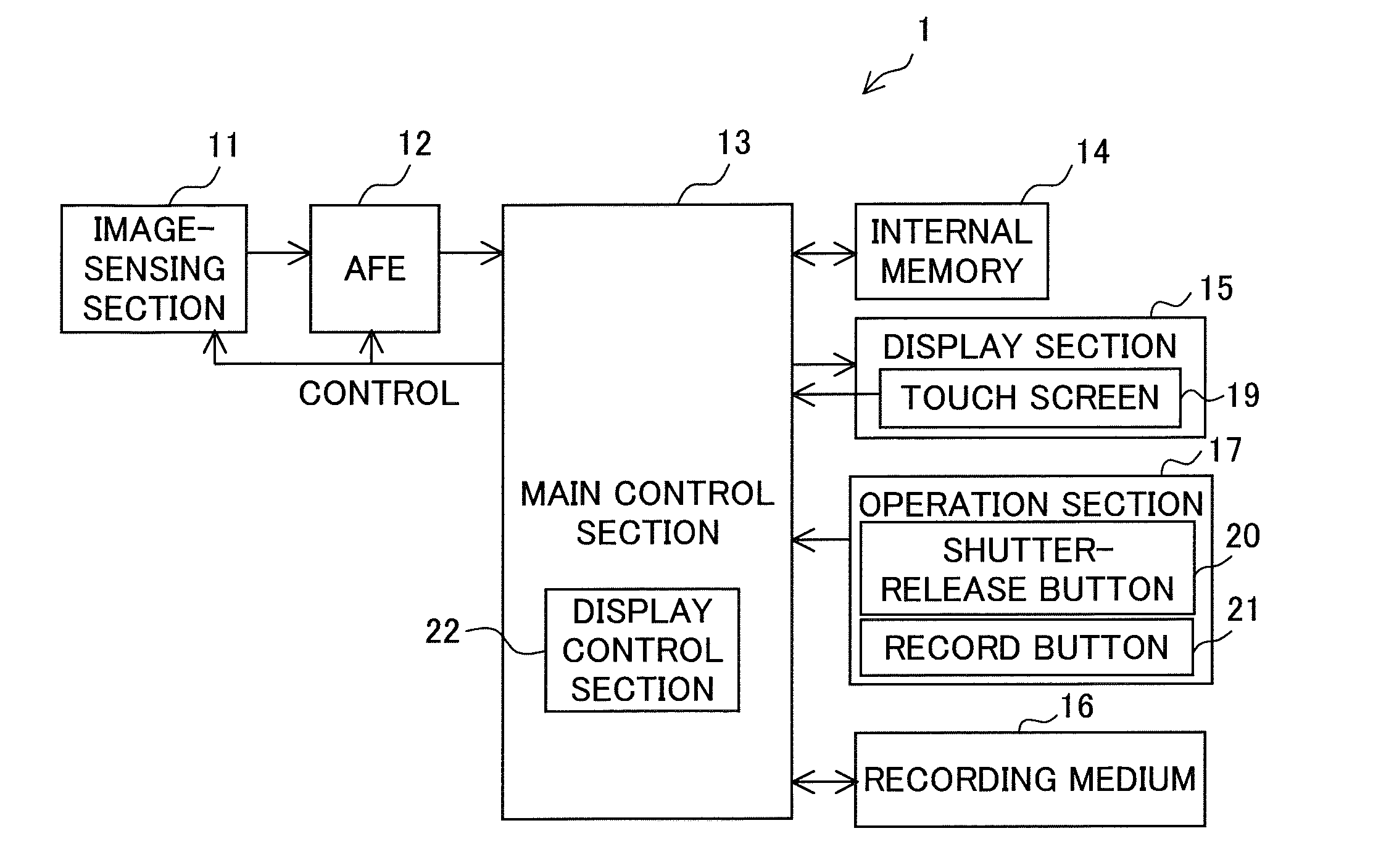
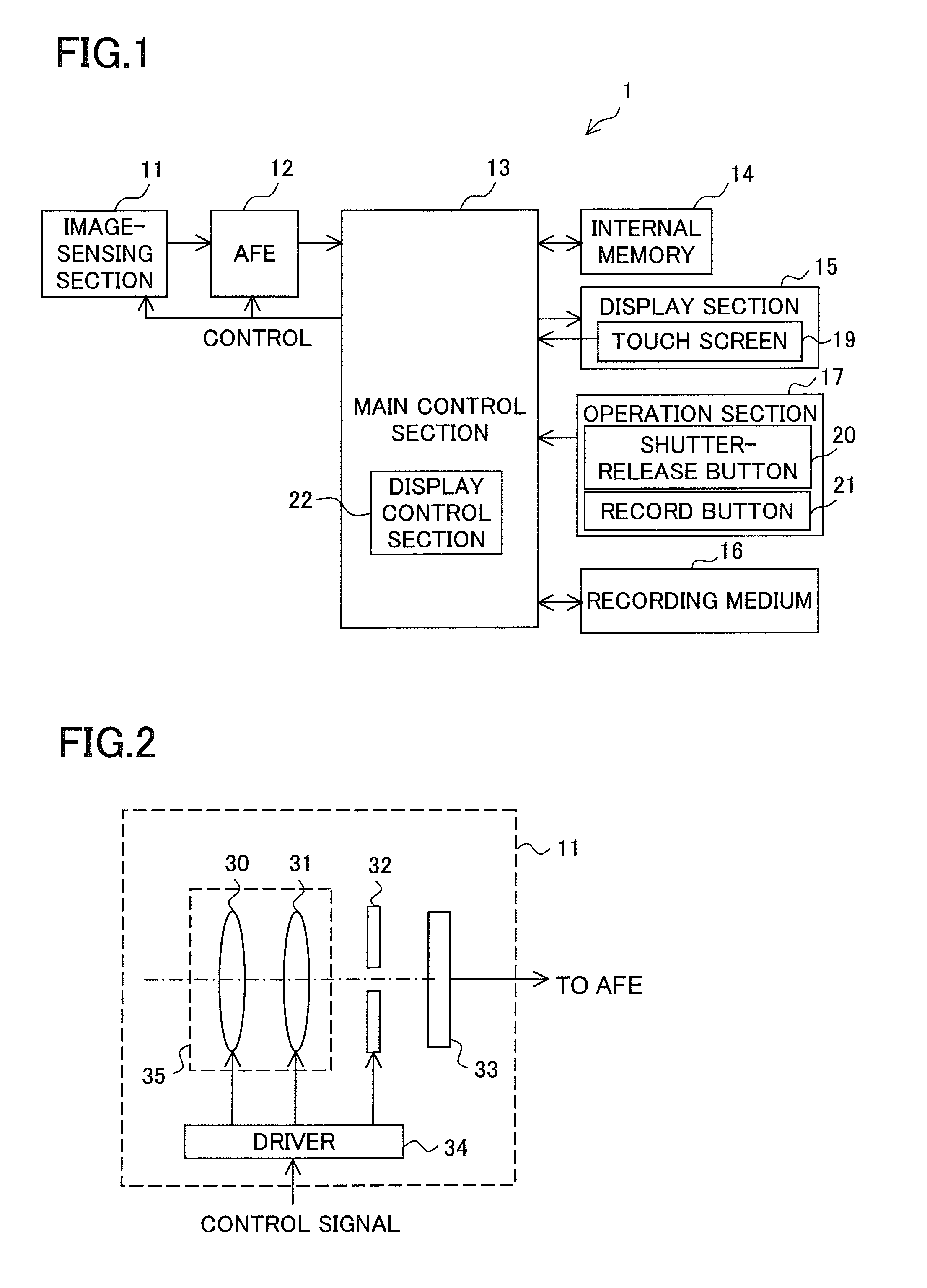
[0069]A first practical example (Example 1) will be described. Example 1 deals with the operation sequence of the image-shooting device 1, with focus placed on the operation for generating the output image. FIG. 11 is a flow chart showing the operation sequence. The operations at steps S11 to S15 are performed in this order. Steps S11 to S13 are performed in shooting mode. Steps S14 and S15 may be performed in shooting mode or in playback mode. In Example 1, and also in Examples 2 to 4 described later, any of the first to third methods of input image generation can be used, and any of the first to fifth methods of composition setting can be used.
[0070]In shooting mode, before input images I[1] to I[n] are shot, the image-sensing section 11 shoots the subject group periodically; the shot images by the image-sensing section 11 before shooting input images I[1] to I[n] are specially called preview images. The display control section 22 in FIG. 1 displays preview images, which are obtai...
example 2
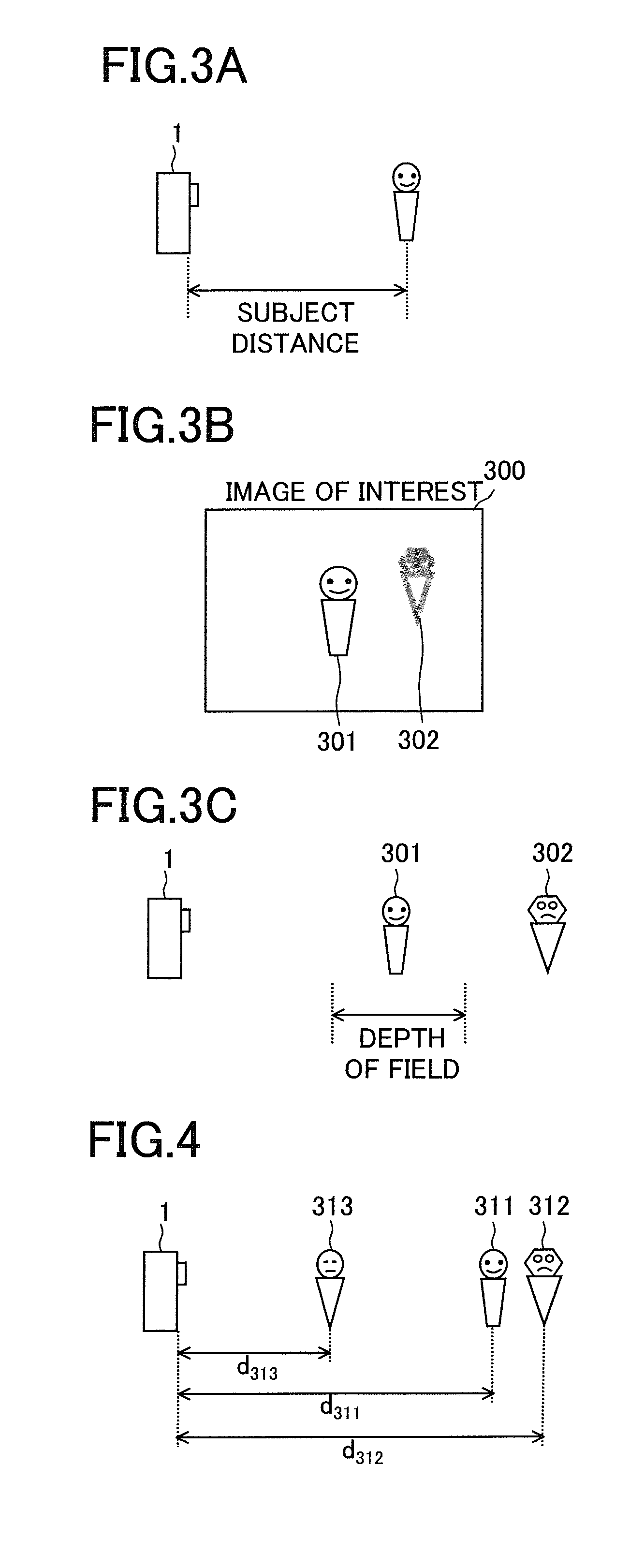
[0081]A second practical example (Example 2) will be described. Example 2, and also Example 3, which will be described later, deals with a specific example of the output image generation processing. In Example 2, the output image generation section 52 generates an output image by use of three-dimensional shape restoration processing whereby the three-dimensional shape of each subject included in the subject group is restored (that is, the output image generation processing may include three-dimensional shape restoration processing). Methods of restoring the three-dimensional shape of each subject from a plurality of input images having parallax are well-known, and therefore no description of such methods will be given. The output image generation section 52 can use any well-known method of restoring a three-dimensional shape (for example, the one disclosed in JP-A-2008-220617).
[0082]The output image generation section 52 restores the three-dimensional shape of each subject included ...
example 3
[0083]A third practical example (Example 3) will be described. In Example 3, the output image generation section 52 generates an output image by use of free-viewpoint image generation processing (that is, the output image generation processing may include free-viewpoint image generation processing). In free-viewpoint image generation processing, from a plurality of input images obtained by shooting a subject from mutually different viewpoints, an image of the subject as viewed from an arbitrary viewpoint (hereinafter referred to as a free-viewpoint image) can be generated. Methods of generating such a free-viewpoint image are well known, and therefore no detailed description of such methods will be given. The output image generation section 52 can use any well-known method of generating a free-viewpoint image (for example, the one disclosed in JP-A-2004-220312).
[0084]By free-viewpoint image generation processing, based on a plurality of input images I[1] to I[n], a free-viewpoint im...
PUM
 Abstract
Description
Claims
Application Information
 - R&D
- Intellectual Property
- Life Sciences
- Materials
- Tech Scout
- Unparalleled Data Quality
- Higher Quality Content
- 60% Fewer Hallucinations
Browse by: Latest US Patents, China's latest patents, Technical Efficacy Thesaurus, Application Domain, Technology Topic, Popular Technical Reports.
© 2025 PatSnap. All rights reserved.Legal|Privacy policy|Modern Slavery Act Transparency Statement|Sitemap|About US| Contact US: help@patsnap.com


