Eureka AIR delivers breakthrough ideas for toughest innovation challenges, trusted by R&D personnel around the world.

Injection mold

Inactive Publication Date: 2012-08-23
CHENG UEI PRECISION IND CO LTD
View PDF7 Cites 2 Cited by
  • Summary
  • Abstract
  • Description
  • Claims
  • Application Information

AI Technical Summary

Benefits of technology

[0007]As described above, the bottom end of the terminal is inserted in the fastening hole through the cavity, and the top end of the terminal is restrained in the groove to avoid the terminal moving upward or downward in the cavity. Moreover, the supporting pole is stretched into the cavity to resist against the top end of the terminal and clip the top end of the terminal between the supporting pole and the second sliding block, so that can further prevent the terminal randomly swaying in the cavity. So the terminal is located in the cavity firmly. As a result, a deformation of the electronic product is avoided accordingly in process of injecting thermoplastic resins into the cavity. Furthermore, production rate of the electronic product can be assured, and cost of manufacturing the electronic product is lowered.

Problems solved by technology

With the fast development of electronic technology, volume of the electronic product is becoming smaller and more delicate so that components of the electronic product are fragile and easily deformed.
However, because the top end of the terminal stretches in the cavity without being restrained by any structures and the terminal is generally slim and small, as a result, the terminal is apt to sway randomly and even deform under the injection attach of the thermoplastic resins.
As a result, the electronic product with the terminal embedded therein often has a lower production rate and the manufacturing cost thereof is accordingly increased.

Method used


Image

  • Injection mold
  • Injection mold

Examples


Embodiment Construction

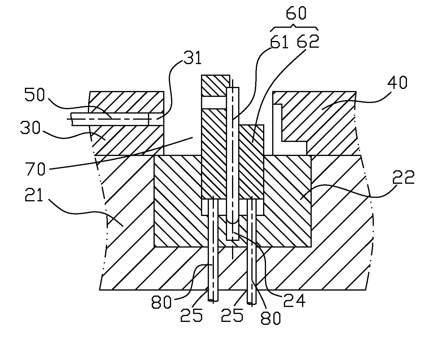
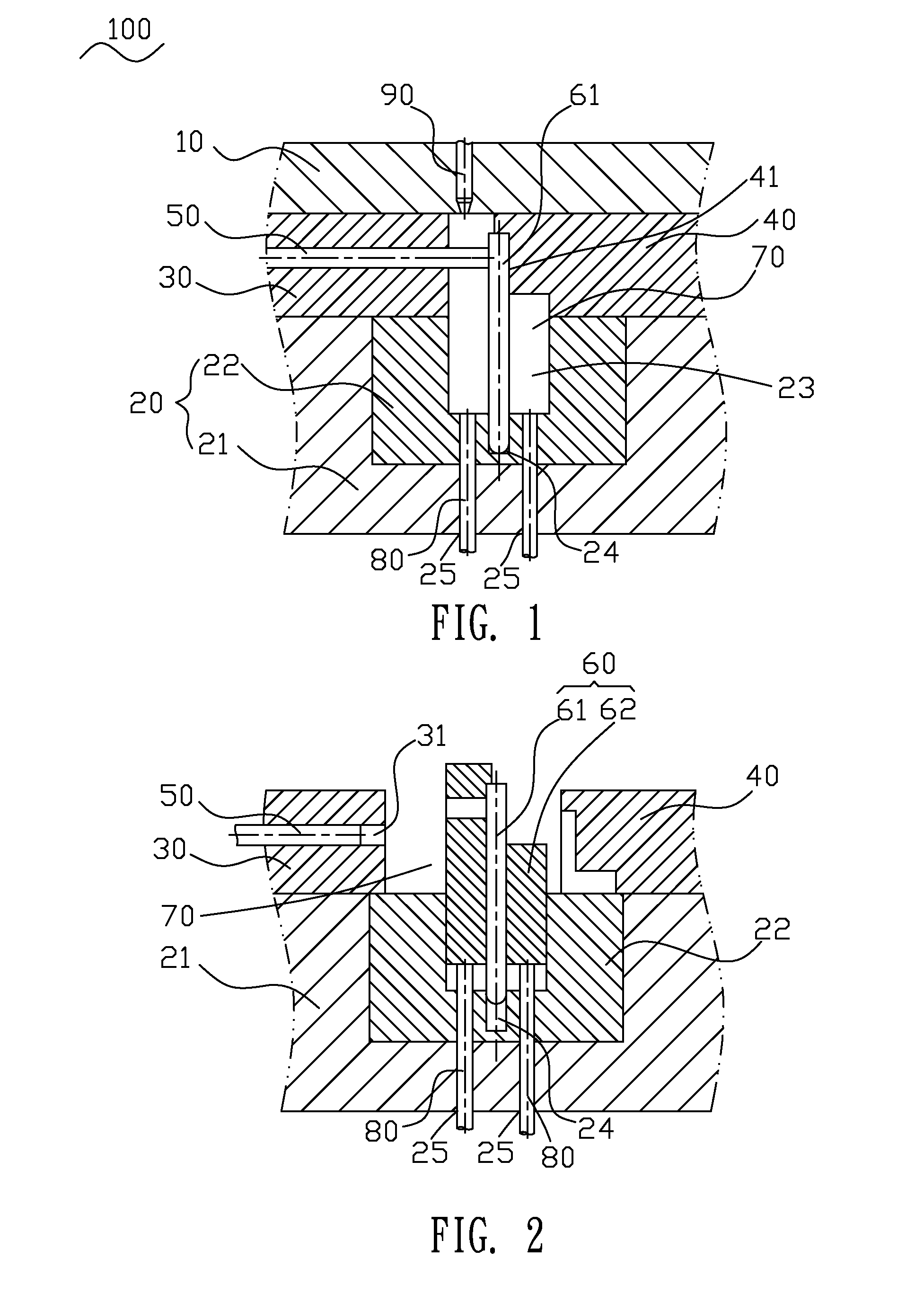
[0011]Referring to FIGS. 1-2, an injection mold 100 for molding an electronic product 60 therein includes a stationary mold 10, a movable mold 20, a first sliding block 30, a second sliding block 40, a supporting pole 50 and two ejector pins 80 mounted on a fixing plate (not shown).

[0012]Referring to FIGS. 1-2, the movable mold 20 has a movable mold plate 21 and a movable mold core 22 mounted in a middle of a top of the movable mold plate 21. A middle of a top of the movable mold core 22 defines an opening 23. A middle of a bottom of the opening 23 extends downward to form a fastening hole 24. The movable mold 20 abreast defines two ejector pin holes 25 each extending vertically to penetrate through the movable mold plate 21 and the movable mold core 22 and communicate with the opening 23. The ejector pin holes 25 are further opened at two opposite sides of the fastening hole 24. A top of the stationary mold 10 defines a sprue channel 90 vertically penetrating therethrough. The firs...


PUM


Abstract

An injection mold for molding an electronic product which has a terminal includes a movable mold, a first sliding block levelly defining a through-hole, a second sliding block, a supporting pole and a stationary mold. A top of the movable mold defines an opening of which a bottom defines a fastening hole for fastening a bottom of the terminal therein. An inner sidewall of the second sliding block defines a groove for restraining a top of the terminal. The first and second sliding blocks are located at two opposite sides of the opening to together define a cavity for molding the electronic product. The supporting pole is movably inserted in the through-hole and stretches into the cavity to resist against the top of the terminal. The stationary mold is positioned on the first and second sliding blocks, and defines a sprue channel connected with the cavity.

Description

BACKGROUND OF THE INVENTION[0001]1. Field of the Invention[0002]The present invention generally relates to an injection mold, and more particularly to an injection mold capable of fastening a terminal therein.[0003]2. The Related Art[0004]With the fast development of electronic technology, volume of the electronic product is becoming smaller and more delicate so that components of the electronic product are fragile and easily deformed. A traditional injection mold for fastening a terminal of the electronic product therein generally includes a stationary mold, a movable mold, a first sliding block and a second sliding block. When the injection mold is used to mold the electronic product with the terminal embedded therein, the first and second sliding blocks are movably mounted on two opposite sides of a top of the movable mold and spaced from each other. The stationary mold defines a sprue channel, and a middle of a top of the movable mold defines a fastening hole. A bottom end of th...

Claims


Application Information

Patent Timeline
IPC IPC(8): B29C45/14
CPCB29C45/14065B29C45/33B29C45/14639
Inventor WANG, XIAN-YUNWU, XIAO-PINGCHIANG, KUN-HSUEH
Owner CHENG UEI PRECISION IND CO LTD
Why Eureka
Eureka Blog
Learn More