High Volume Carpule System

a carpule system and high-volume technology, applied in the field of high-volume carpule systems, can solve the problems of limited design, limited design, and limited design, and achieve the effects of high capacity, and high volume of anestheti

Inactive Publication Date: 2012-08-23
MCLELLAND BRYAN W DR
View PDF13 Cites 7 Cited by
  • Summary
  • Abstract
  • Description
  • Claims
  • Application Information

AI Technical Summary

Benefits of technology

[0010]A system for storing and dispensing a high volume of anesthetic to a patient. The invention generally relates to a high volume carpule system. A preferred embodiment of the high volume carpule system generally includes a syringe having a modified carpule cavity comprised of an upper ring member and a lower ring member which are linked together by a first side member and a second side member. The side members are oriented in such a manner as to allow a pair of slots through which side portions of a high capacity carpule may extend. A high capacity carpule comprised of a substantially cylindrical shape with an elongated cross-section is disclosed for use with the modified carpule cavity. In an alternate embodiment, a second high capacity carpule design is disclosed for use with conventional, prior art syringes. By using the present invention, a dentist or surgeon may administer a higher volume of anesthetic without having to switch carpules within a syringe.

Problems solved by technology

Currently commercially available carpule designs are generally limited to 1.7-1.8 milliliters by volume.
Such existing designs are typically limited so that they fit within a mouth and are not too long and unwieldy.
Further, existing designs are generally limited to a purely cylindrical shape due to the difficulty in sealing complex geometries due to the high pressure that may be applied to the stopper.
Further, the odd size of commercially available carpules (i.e. lidocaine carpules) complicates the delivery of anesthetic due to the calculations that must be performed by a dentist, oral surgeon or their staff to determine the proper amount of anesthetic to deliver to the patient via the syringe.

Method used


Image

  • High Volume Carpule System
  • High Volume Carpule System
  • High Volume Carpule System

Examples


Embodiment Construction

A. Preferred Embodiment

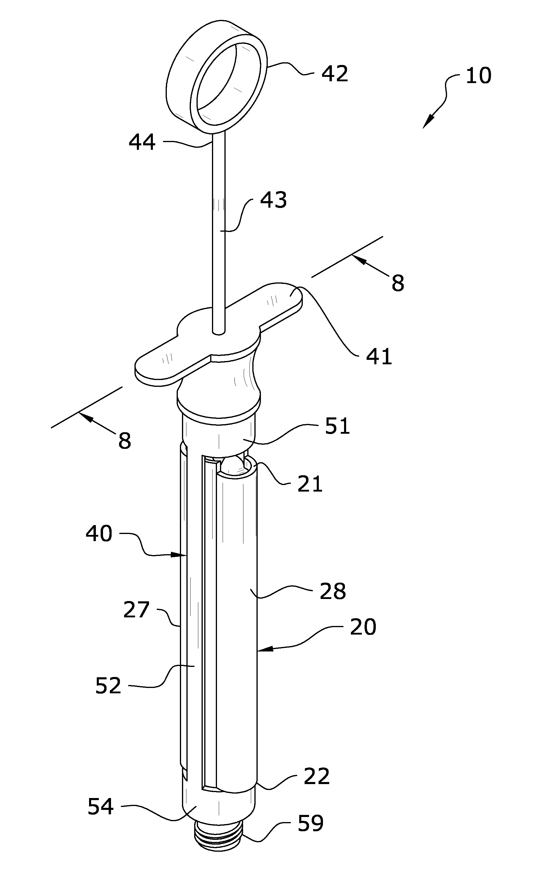
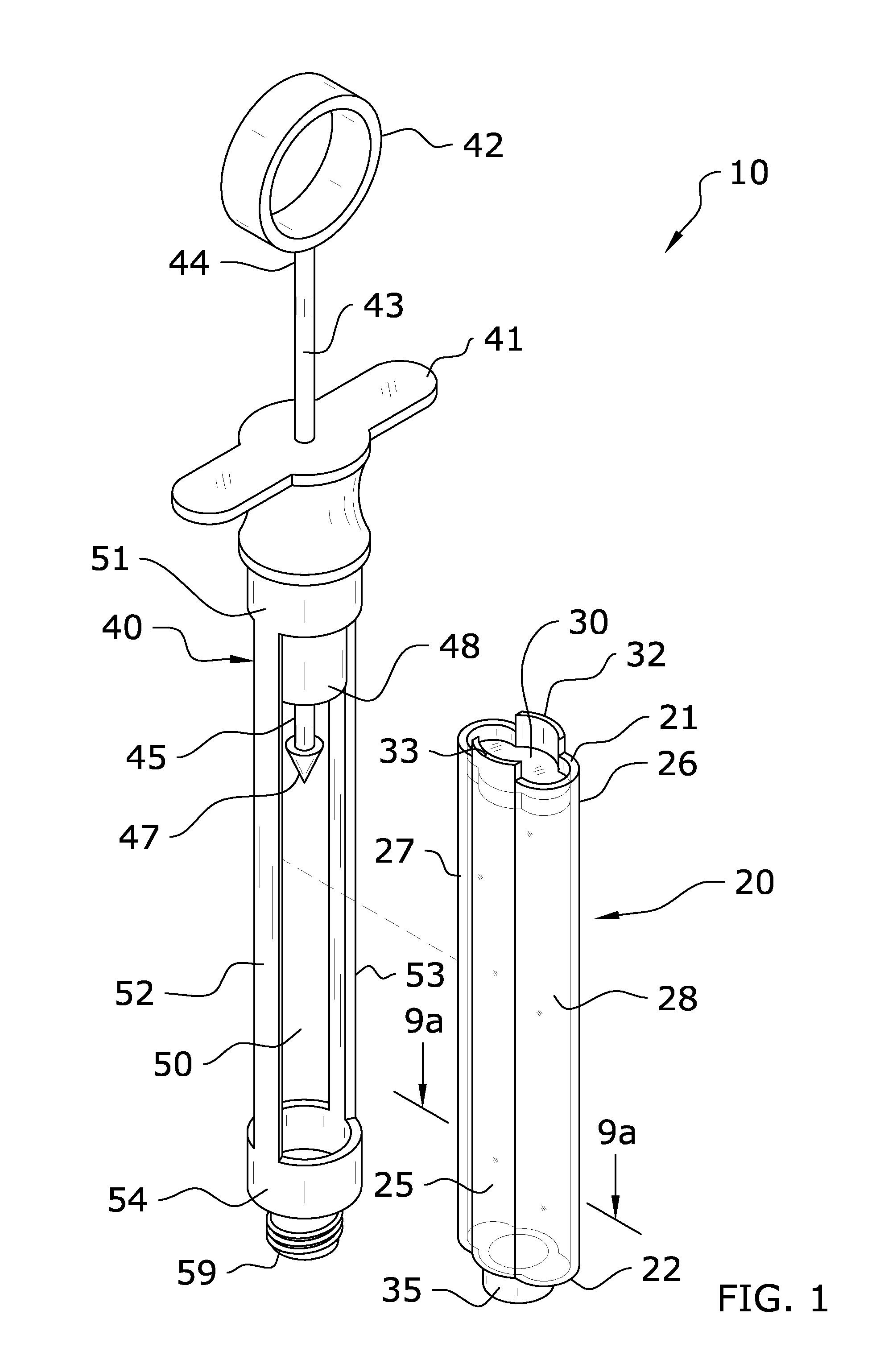
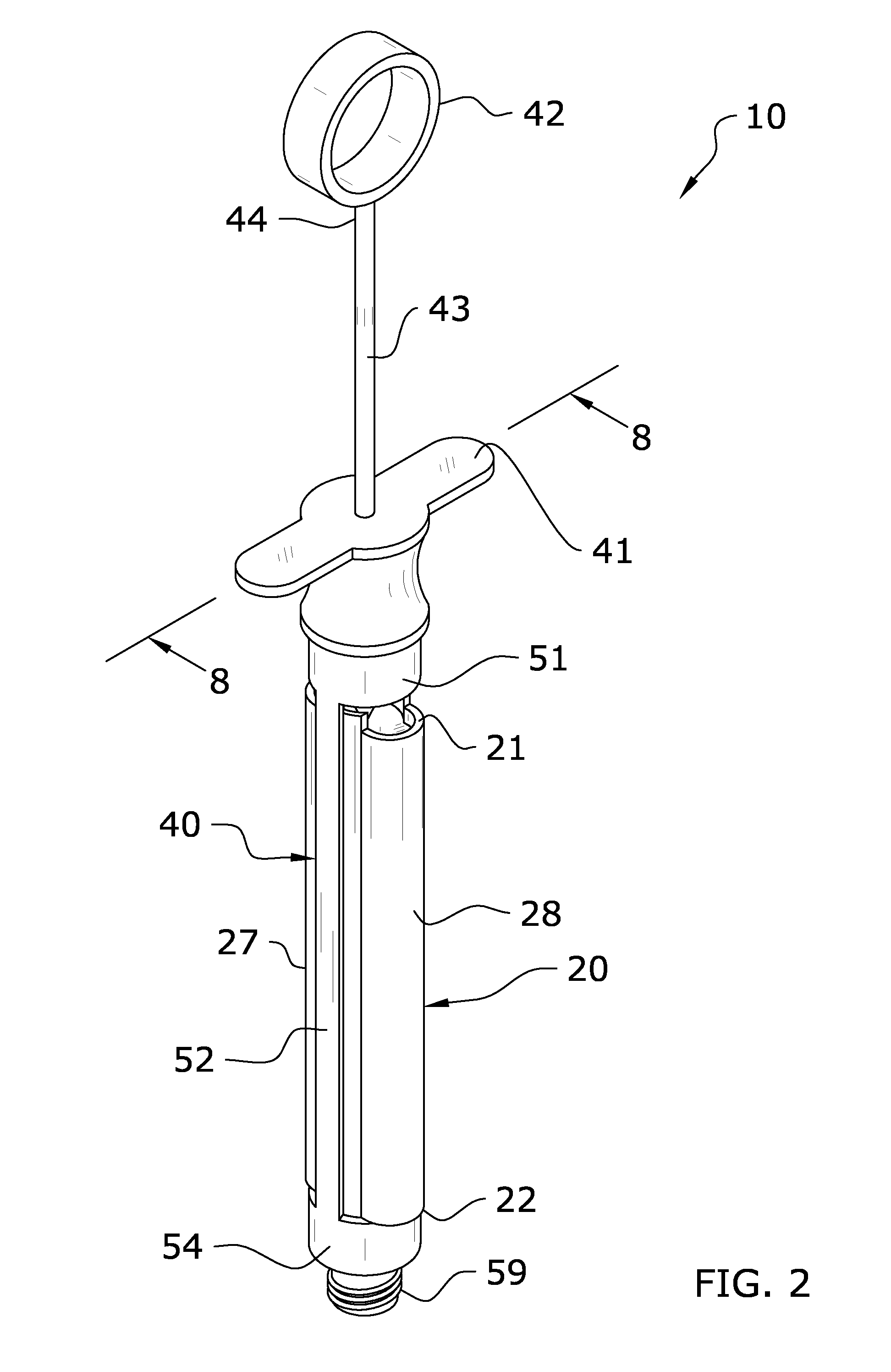
[0023]Turning now descriptively to the drawings, in which similar reference characters denote similar elements throughout the several views, FIGS. 1 through 4 illustrate a preferred embodiment of a high volume carpule system 10. The preferred embodiment of the present invention utilizes a high capacity carpule 20 and a syringe 40. The syringe 40 utilizes a modified carpule cavity 50 in the form of a frame comprised of an upper ring member 51, lower ring member 54, first side member 52 and second side member 53. The carpule 20 includes a rounded first side portion 27 and second side portion 28, wherein the first and second side portions 27, 28 extend out the respective sides of the carpule cavity 50.

[0024]i. Syringe.

[0025]As shown in FIG. 1, the present invention utilizes a syringe 40 for delivering the anesthetic stored within the carpule 20. The syringe 40 is generally comprised of a design which has been modified when compared to conventional syringe 40 desi...


PUM


Abstract

A high volume carpule system for storing and dispensing a high volume of anesthetic to a patient. A preferred embodiment of the high volume carpule system generally includes a syringe having a modified carpule cavity comprised of an upper ring member and a lower ring member which are linked together by a first side member and a second side member. The side members are oriented in such a manner as to allow a pair of slots through which side portions of a high capacity carpule may extend. A high capacity carpule comprised of a substantially cylindrical shape with an elongated cross-section is disclosed for use with the modified carpule cavity. In an alternate embodiment, a second high capacity carpule design is disclosed for use with conventional, prior art syringes. By using the present invention, a dentist or surgeon may administer a higher volume of anesthetic without having to switch carpules within a syringe.

Description

CROSS REFERENCE TO RELATED APPLICATIONS[0001]Not applicable to this application.STATEMENT REGARDING FEDERALLY SPONSORED RESEARCH OR DEVELOPMENT[0002]Not applicable to this application.BACKGROUND OF THE INVENTION[0003]1. Field of the Invention[0004]The present invention relates generally to a new and improved carpule design and more specifically it relates to a high volume carpule system for storing and dispensing a high volume of anesthetic to a patient.[0005]2. Description of the Related Art[0006]Any discussion of the related art throughout the specification should in no way be considered as an admission that such related art is widely known or forms part of common general knowledge in the field.[0007]Carpules have been in use for years for procedures requiring the application of anesthetic or other compositions with a syringe. Previously existing and widely available carpules for use by dentists or oral surgeons have conventionally been available in certain sizes to fit the conven...

Claims


Application Information

Patent Timeline
Patent Type & Authority Applications(United States)
IPC IPC(8): A61C19/08
CPCA61C19/08A61M5/24A61M2005/2437A61M5/3129A61M2005/2414A61J1/062
Inventor MCLELLAND, BRYAN W.PALMER, RANDALL T.
Owner MCLELLAND BRYAN W DR
Why Eureka
Try Eureka