Robotic claw and robot using same

Active Publication Date: 2012-08-30
SHENZHENSHI YUZHAN PRECISION TECH CO LTD
View PDF7 Cites 4 Cited by
  • Summary
  • Abstract
  • Description
  • Claims
  • Application Information

AI Technical Summary

Problems solved by technology

However, if the diameter of the balls is unduly small, it is difficult for the robotic claw to clamp the object due to a smaller friction force produced between the balls and the object.

Method used


Image

  • Robotic claw and robot using same
  • Robotic claw and robot using same
  • Robotic claw and robot using same

Examples


Embodiment Construction

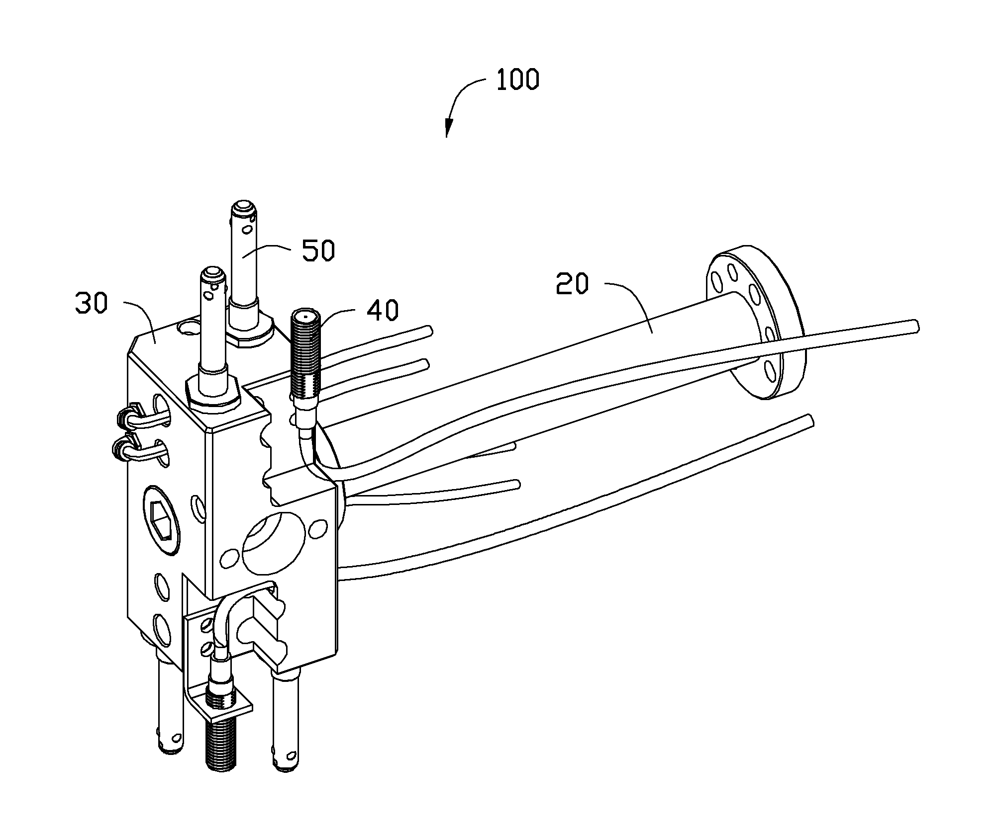
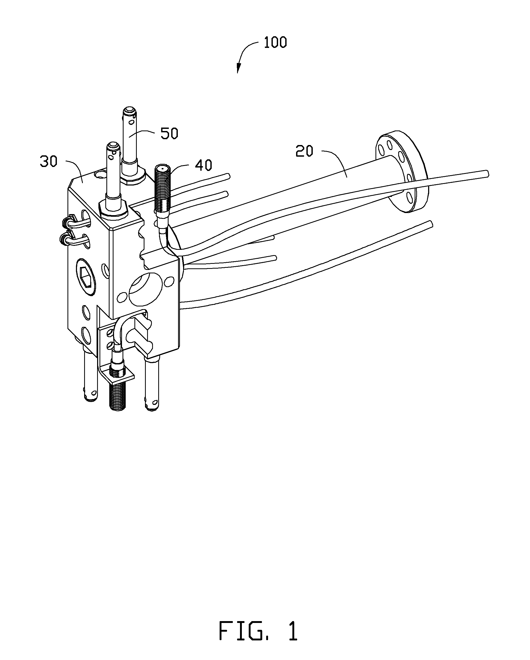
[0012]Referring to FIGS. 1 and 2, an embodiment of a robot 100 includes a robotic arm 20, an air cylinder 30, a pair of position sensors 40, and four robotic claws 50. The cylinder 30 is fixed to an end of the arm 20. The sensors 40 and the claws 50 are both assembled on the cylinder 30.

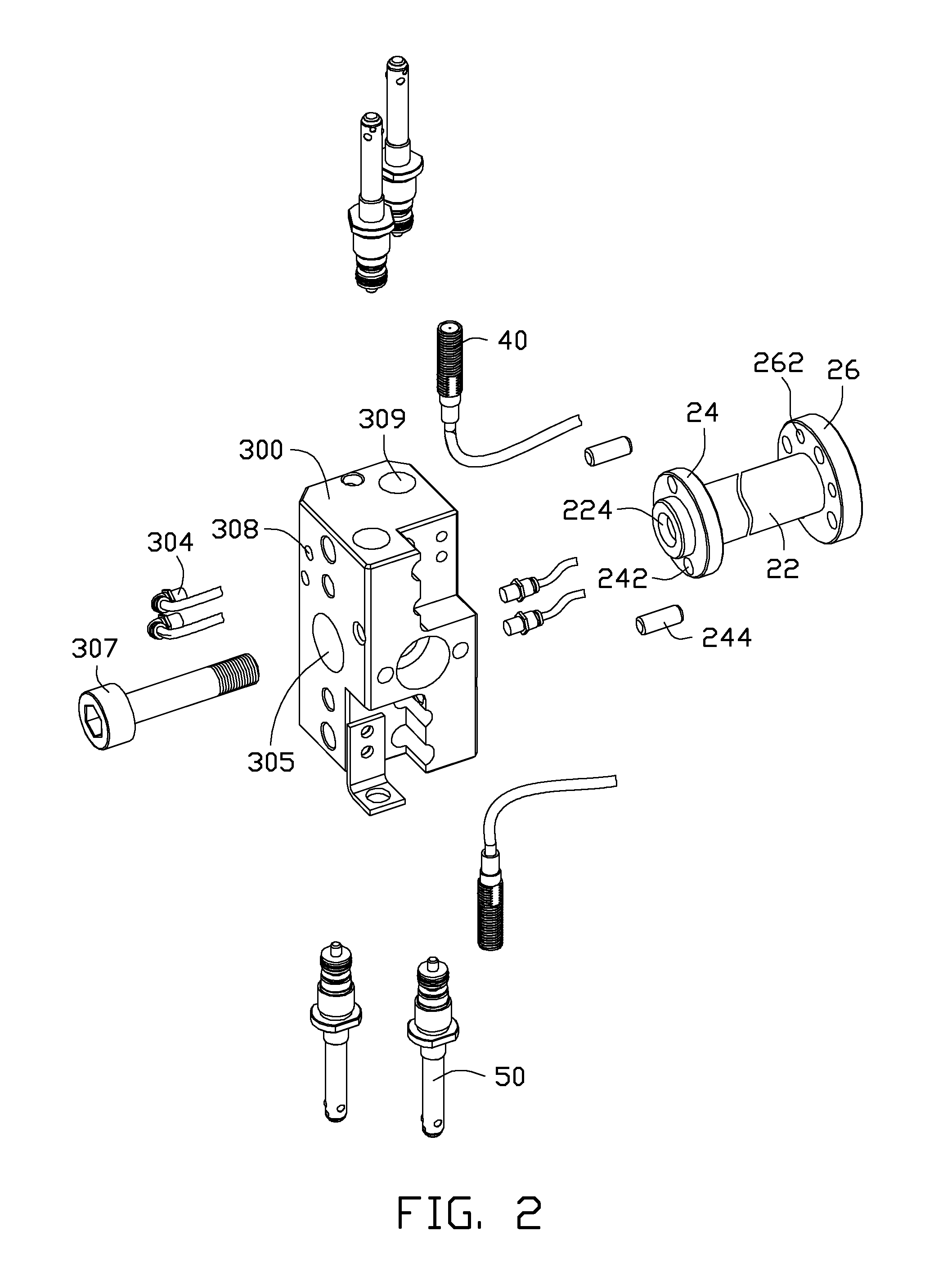
[0013]The arm 20 is connected to a driving mechanism (not shown) of the robot 100. The cylinder 30 and the claws 50 move as the arm 20 moves. In the illustrated embodiment, the arm 20 is substantially a hollow cylinder for decreasing the total weight of the robot 100. The arm 20 includes a cylindrical base portion 22, a first flange joint 24, and a second flange joint 26. The flange joints 24, 26 are formed on the base portion 22 adjacent to opposite ends of the base portion 22 respectively. The flange joint 24 is adjacent to the cylinder 30 and the flange joint 26 is away from the cylinder 30. Two threaded through holes 242 are defined in the flange joint 24. The cylinder 30 is fixed to the arm 20 b...


PUM


Abstract

A robotic claw includes a sleeve, a rod, a plurality of balls and a plunger. The sleeve comprises a mounting portion and a clamping portion. A mounting hole defined at an end of the mounting portion. A plurality of receiving through holes defined in the clamping portion, and an assembling hole communicating with the receiving through hole, and is defined at an end of the clamping portion. The balls are movably received in the receiving through holes correspondingly. The rod comprises an urging portion movably received in the sleeve to push the balls toward the receiving through holes. The plunger seals the assembling hole to prevent the balls from dropping out of the receiving through holes, and the balls can be mounted in the receiving through holes through the assembling hole.

Description

BACKGROUND[0001]1. Technical Field[0002]The present disclosure relates to holding structures, particularly to a robotic claw and a robot using the claw.[0003]2. Description of Related Art[0004]Presently, robots are widespread in automatic production devices. A robotic claw is an important part of a robot for gripping an object, e.g., a workpiece. One such robotic claw generally includes a sleeve, a rod, and a plurality of balls. The sleeve includes a clamping portion and a mounting portion connected to the clamping portion. The clamping portion defines a plurality of receiving through holes in an inner wall of the clamping portion. The balls are mounted in the clamping portion of the sleeve and correspond to the receiving through holes. An object held by the robotic claw defines a latching hole and a plurality of latching grooves are defined in a side wall of the latching hole corresponding to the receiving through holes. The rod is moveably received in the sleeve to push the balls ...

Claims


Application Information

Patent Timeline
IPC IPC(8): B25J18/00F16D1/00
CPCY10T74/20311B25J15/0047Y10T403/75
Inventor YEH, CHI-HSIENQIN, ZHONGLI, JIE
Owner SHENZHENSHI YUZHAN PRECISION TECH CO LTD
Why Eureka
Try Eureka