Antenna Assembly

a technology of antenna and assembly, which is applied in the direction of antenna details, antenna adaptation in movable bodies, antennas, etc., can solve the problems of small cost of any of these changes, and achieve the effects of cost saving, improved performance, and attractive exterior appearan

Active Publication Date: 2012-08-30
HARADA IND OF AMERICA
View PDF3 Cites 7 Cited by
  • Summary
  • Abstract
  • Description
  • Claims
  • Application Information

AI Technical Summary

Benefits of technology

[0007]At least one aspect of the present invention provides for an antenna assembly including an environmentally-sealed housing for disposal inside of a non-metallic structure of a vehicle, e.g. a bumper, a spoiler, an air dam or a deck lid. A printed circuit board is disposed at least partially within the housing, and the printed circuit board includes a trace extending in a longitudinal direction through a plurality of second order Hilbert Curves. The trace is configured to receive amplitude modulation (AM), frequency modulated (FM) and / or high definition (HD) radio signals. Because the antenna assembly is disposed within the non-metallic structure of the vehicle, it is out of sight for the driver and others outside of the vehicle, thus allowing for the vehicle to have a more aesthetically appealing exterior appearance. Further, the antenna assembly can be as large as the non-metallic structure within which it is disposed and is not limited to the constraints of the rear windshield. Thus, the trace may be made longer than other comparable glass-embedded antennas which could lead to improved performance without the drawbacks associated with glass-embedded antennas discussed above.
[0008]The antenna assembly is also beneficial because it can be used in any type of vehicle, thus allowing for cost savings through manufacturing of scale. For example, the same antenna assembly could be placed in a deck of a sport utility vehicle, the spoiler of a sports car or the bumper of a large passenger vehicle.
[0009]Additionally, through simple adjustments, the antenna assembly can also be reconfigured to optimize its performance in any type of vehicle. For example, the material of the trace, the width of the trace, the number of Hilbert Curves through which the trace extends or the dimensions of the Hilburt Curves could all be modified for any particular vehicle. Any of these modifications could have an impact on the performance of the antenna assembly, and the cost of any of these changes could be very small.
[0010]According to another aspect of the present invention, an additional trace is printed on the printed circuit board opposite of the trace with the Hilbert Curves. The additional trace can be configured for receiving, for example, remote keyless entry signals and / or digital audio band (DAB) radio signals. Thus, the additional functionality of having an externally mounted remote keyless entry antenna and / or DAB antenna is gained with the only additional cost being the printing of a second trace on the printed circuit board. The additional trace is printed on the side of the board opposite of the first trace discussed above for minimizing the size of the printed circuit board, and thus the entire antenna assembly.

Problems solved by technology

Any of these modifications could have an impact on the performance of the antenna assembly, and the cost of any of these changes could be very small.

Method used


Image

  • Antenna Assembly
  • Antenna Assembly
  • Antenna Assembly

Examples


Embodiment Construction

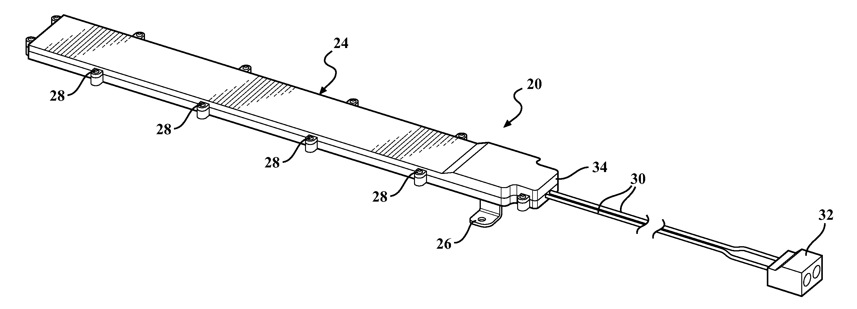
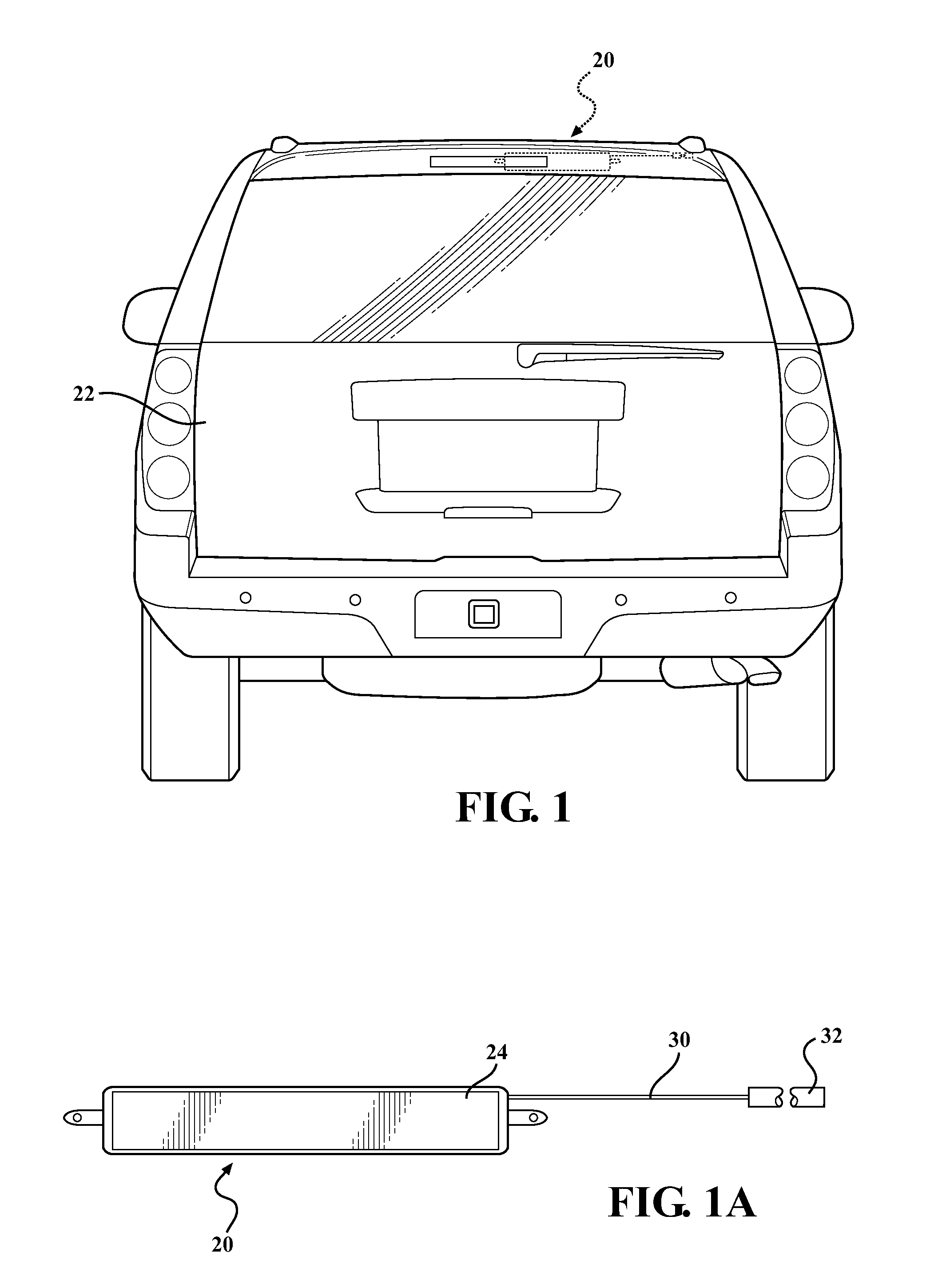
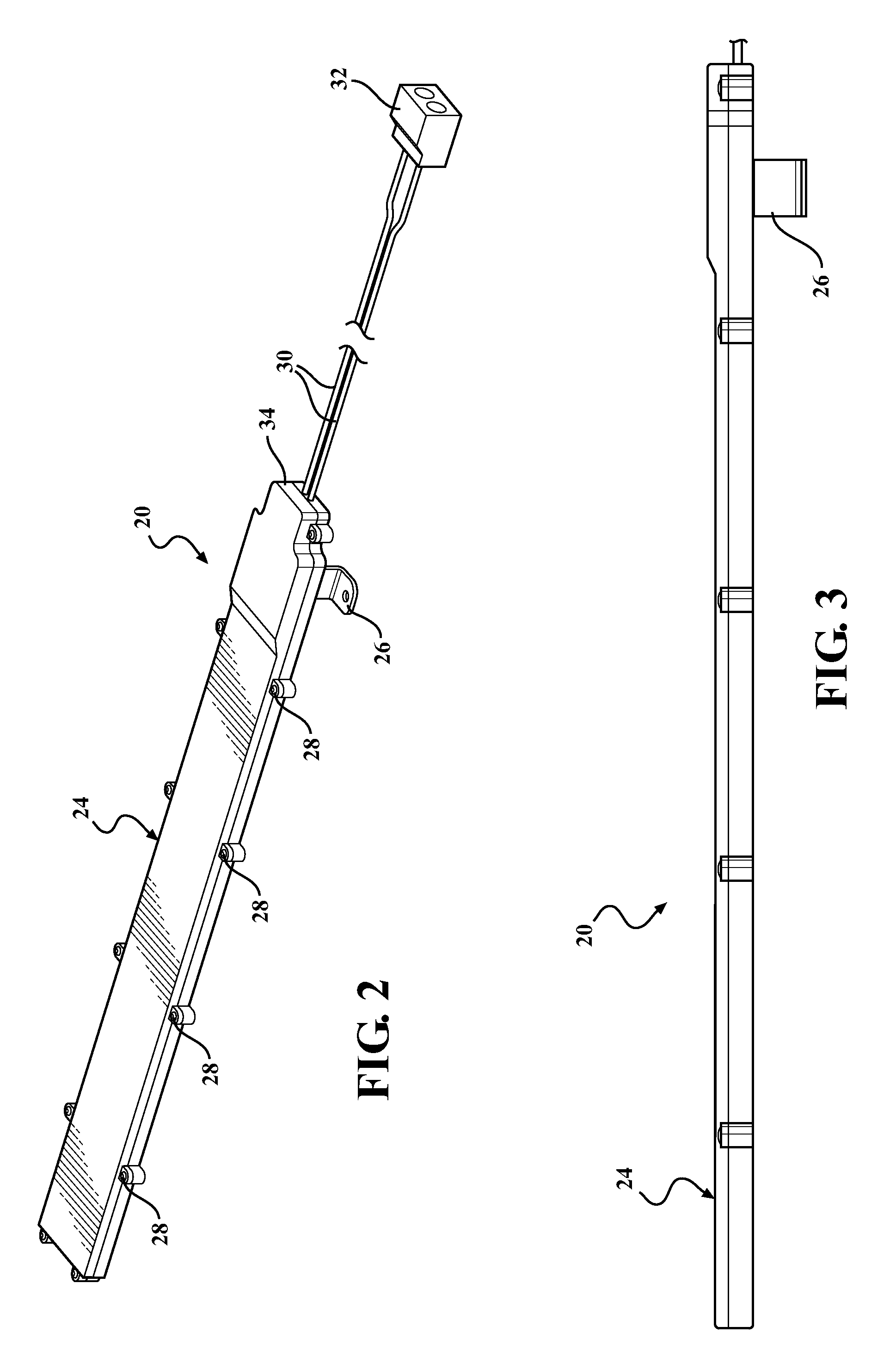
[0028]Referring to the drawings wherein like numerals indicate corresponding parts throughout the several views, an exemplary antenna assembly 20 is generally shown in FIG. 1A for disposal in the vehicle 22 of FIG. 1. In the exemplary embodiment, the antenna assembly 20 is positioned within an air dam of a typical sport utility vehicle 22, which may result in improved reception since the air dam is so high on the vehicle. However, it should be appreciated that the antenna assembly 20 could be mounted within a wide variety of non-metallic structures on the vehicle 22, including, for example, a spoiler or a bumper. Although the structure containing the antenna assembly 20 should be non-metallic to allow for maximum performance, a metal ground point is required, as will be discussed in further detail below.

[0029]As will be discussed in further detail below, the antenna assembly 20 is configured to receive amplitude modulation (AM), frequency modulation (FM), high definition (HD), digit...


PUM


Abstract

An antenna assembly for a vehicle including an environmentally sealed housing and a printed circuit board. The printed circuit board is at least partially disposed within the environmentally sealed housing and extends through a plurality of second order Hilbert Curves which are arranged in side-by-side relationship with one another. The antenna assembly is preferably disposed within a non-metallic structure of the vehicle, and therefore, the antenna assembly is hidden from view, thereby allowing the vehicle to have a more aesthetically pleasing external appearance. Additionally, the length of the trace is limited by the space inside of the non-metallic structure, and therefore, depending on the size of the non-metallic structure, a very long trace having a high performance could be printed on the printed circuit board.

Description

CROSS REFERENCE TO RELATED APPLICATION[0001]This application claims the benefit of U.S. Provisional Application Ser. No. 61 / 446,722 filed Feb. 25, 2011, entitled “Antenna Assembly,” the entire disclosure of the application being considered part of the disclosure of this application and hereby incorporated by reference.BACKGROUND OF THE INVENTION[0002]1. Field of the Invention[0003]The present invention relates to an antenna for a vehicle. More specifically, the present invention relates to a printed circuit board fractal antenna.[0004]2. Description of the Prior Art[0005]Traditionally, radio antennas are disposed on the exterior of the vehicle and in the plain view of both the driver and others outside of the vehicle, which some people consider to be visually unappealing. In order to enhance the external appearance of their vehicles, some automobile manufacturers have developed antennas that are built into the rear windshields of their vehicles. However, such glass-embedded antennas...

Claims


Application Information

Patent Timeline
Patent Type & Authority Applications(United States)
IPC IPC(8): H01Q1/32
CPCH01Q1/3283H01Q21/28H01Q9/42
Inventor MERRICK, MICHAELGRAY, MATTHEW GORDONLARASHI, ERVINLEELARATNE, RUSBREDEN, RICHARD
Owner HARADA IND OF AMERICA
Why Eureka
Try Eureka