Projection type image display device
a projection type, image display technology, applied in the direction of instruments, color television details, mountings, etc., can solve the problems of index value indicating the focus state, difficult to precisely calculate, and inability to adjust the focus with high precision
- Summary
- Abstract
- Description
- Claims
- Application Information
AI Technical Summary
Problems solved by technology
Method used
Image

Examples
first embodiment
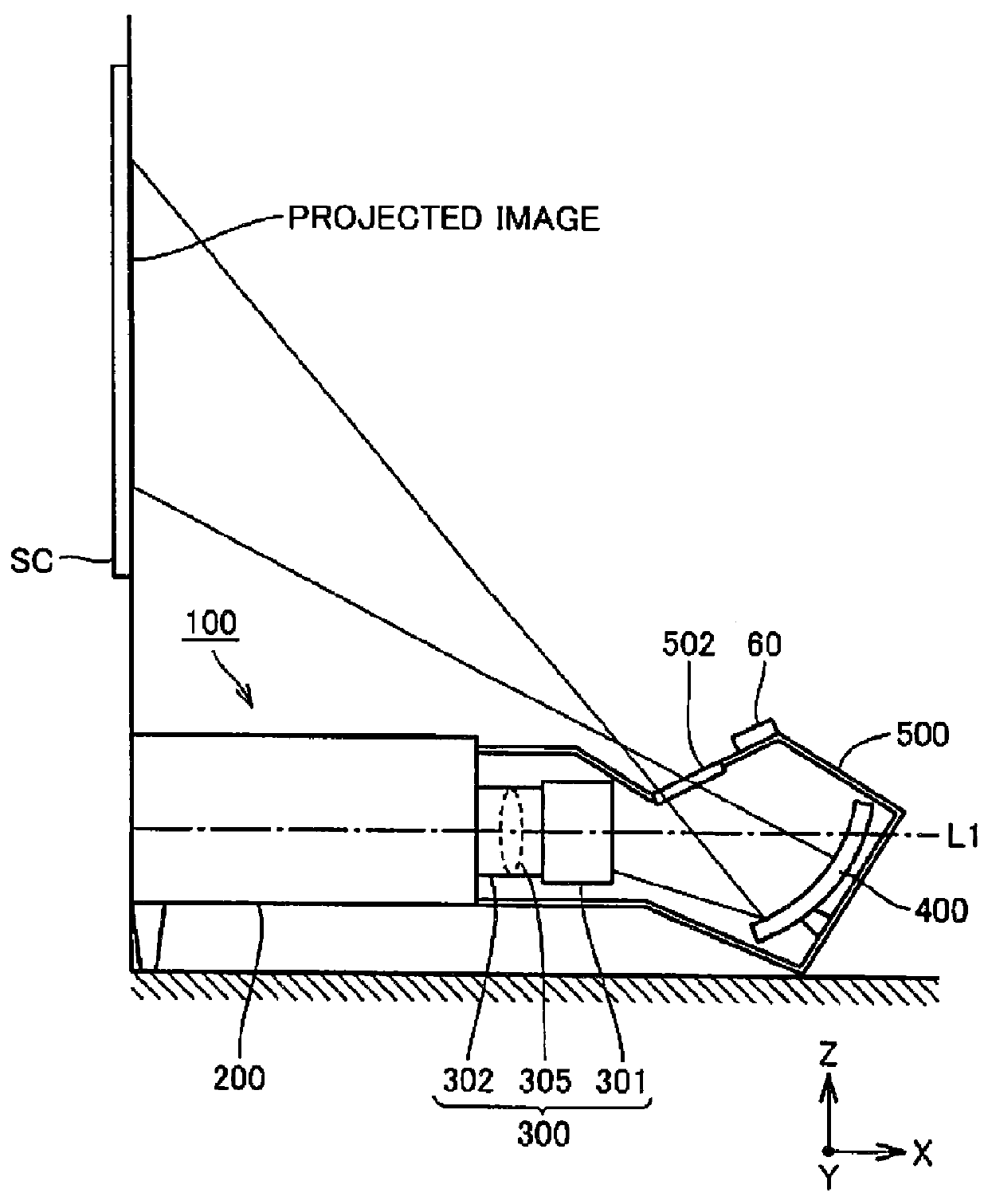
[0028]FIG. 1 is a schematic view of a configuration of a projection type image display device according to an embodiment of the present invention.
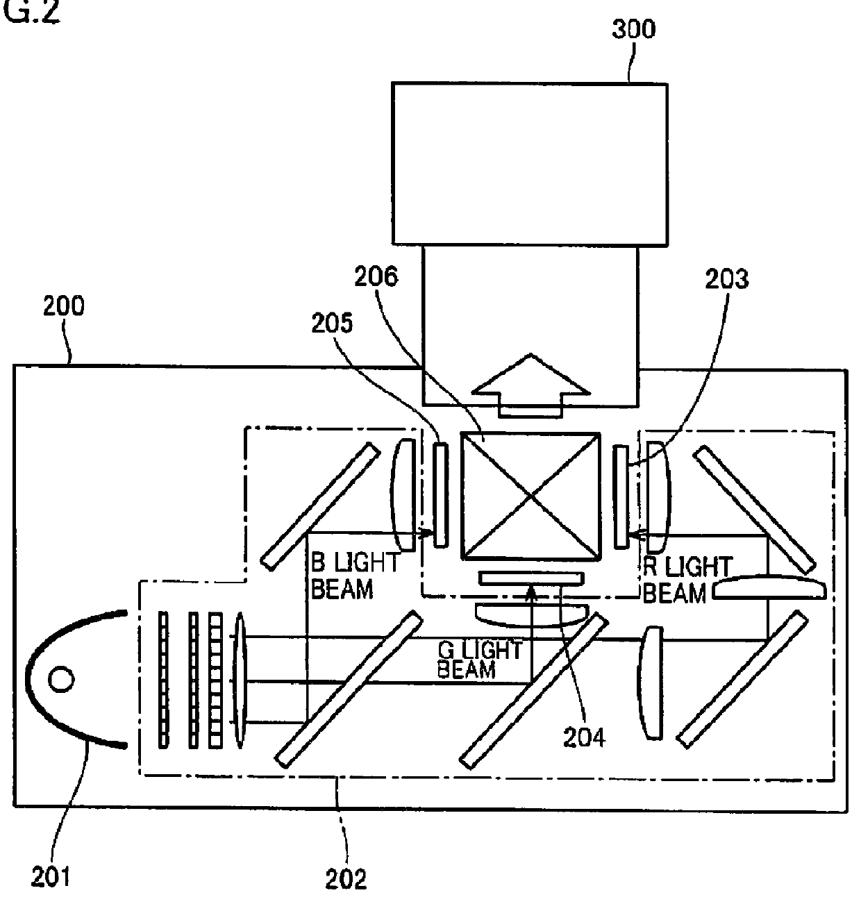
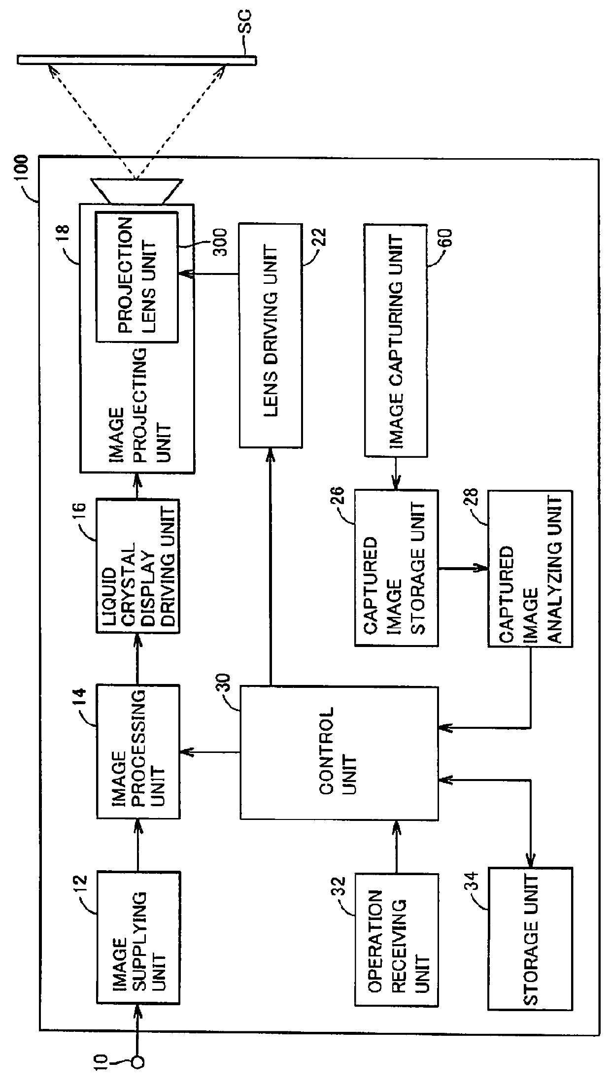
[0029]Referring to FIG. 1, a projection type image display device (hereinafter, referred to as “projector”) 100 includes an optical engine 200, a projection lens unit 300, a reflective minor 400, a cover 500, and an image capturing unit 60. It should be noted that projector 100 also has a component for outputting a sound such as a speaker, a circuit board for electrically controlling a component of optical engine 200 and an audio output unit, and the like, but a part of components including these components are not illustrated in FIG. 1.
[0030]Optical engine 200 includes a light source (not shown). Optical engine 200 generates image light by modulating, in accordance with an input image signal, light emitted from the light source. Projection lens unit 300 is attached to optical engine 200. The image light emitted from optical engine 200 ent...
second embodiment
[0096]In a second embodiment of the present invention, as another manner of the process of adjusting the focus adjustment pattern in the present invention, the focus adjustment pattern is adjusted to compensate a resolution difference in the captured image. With reference to figures, the following describes the process of adjusting the focus adjustment pattern in the second embodiment of the present invention.
[0097]FIG. 11 shows one exemplary focus adjustment pattern adjusted by the process of adjusting in the second embodiment of the present invention.
[0098]Referring to FIG. 11, the adjusted focus adjustment pattern is constituted by black color regions and white color regions arranged alternately in the lateral direction as with the focus adjustment pattern shown in FIG. 4. In the adjusted focus adjustment pattern, each of the color regions has a lateral width continuously changing in the longitudinal direction. Specifically, each of the white color regions has a width gradually i...
third embodiment
[0112]In a third embodiment of the present invention, as another manner of the process of adjusting the focus adjustment pattern in the present invention, the focus adjustment pattern is adjusted to compensate a contrast difference and a resolution difference in the captured image. With reference to figures, the following describes the process of adjusting the focus adjustment pattern in the third embodiment of the present invention.
[0113]FIG. 14 shows one exemplary focus adjustment pattern adjusted by the process of adjusting in the third embodiment of the present invention.
[0114]Referring to FIG. 14, the adjusted focus adjustment pattern is constituted by black color regions and white color regions arranged alternately in the lateral direction as with the focus adjustment pattern shown in FIG. 4. In the adjusted focus adjustment pattern, each of the color regions has gradation in which the brightness is changed continuously in the longitudinal direction. Specifically, each of the ...
PUM
 Abstract
Description
Claims
Application Information
 - R&D
- Intellectual Property
- Life Sciences
- Materials
- Tech Scout
- Unparalleled Data Quality
- Higher Quality Content
- 60% Fewer Hallucinations
Browse by: Latest US Patents, China's latest patents, Technical Efficacy Thesaurus, Application Domain, Technology Topic, Popular Technical Reports.
© 2025 PatSnap. All rights reserved.Legal|Privacy policy|Modern Slavery Act Transparency Statement|Sitemap|About US| Contact US: help@patsnap.com