Network communication method and network node device

Active Publication Date: 2012-08-30
HUAWEI TECH CO LTD
View PDF22 Cites 28 Cited by
  • Summary
  • Abstract
  • Description
  • Claims
  • Application Information

AI Technical Summary

Benefits of technology

[0008]According to some embodiments of the present invention, the label is allocated through the layer 2 label allocation protocol, thus maintainin

Problems solved by technology

If it is required to support PWE3 (pseudo wire emulation edge-to-edge, pseudo wire emulation edge-to-edge), not only a control plane of a layer 2 network node needs to be improved to upgrade the control plane to layer 3, but also a data plane of th

Method used


Image

  • Network communication method and network node device
  • Network communication method and network node device
  • Network communication method and network node device

Examples


Embodiment Construction

[0022]In order to make the foregoing objectives, features, and advantages of the embodiments of the present invention more obvious and comprehensible, the embodiments of the present invention are further described in detail below with reference to the accompanying drawings and specific embodiments.

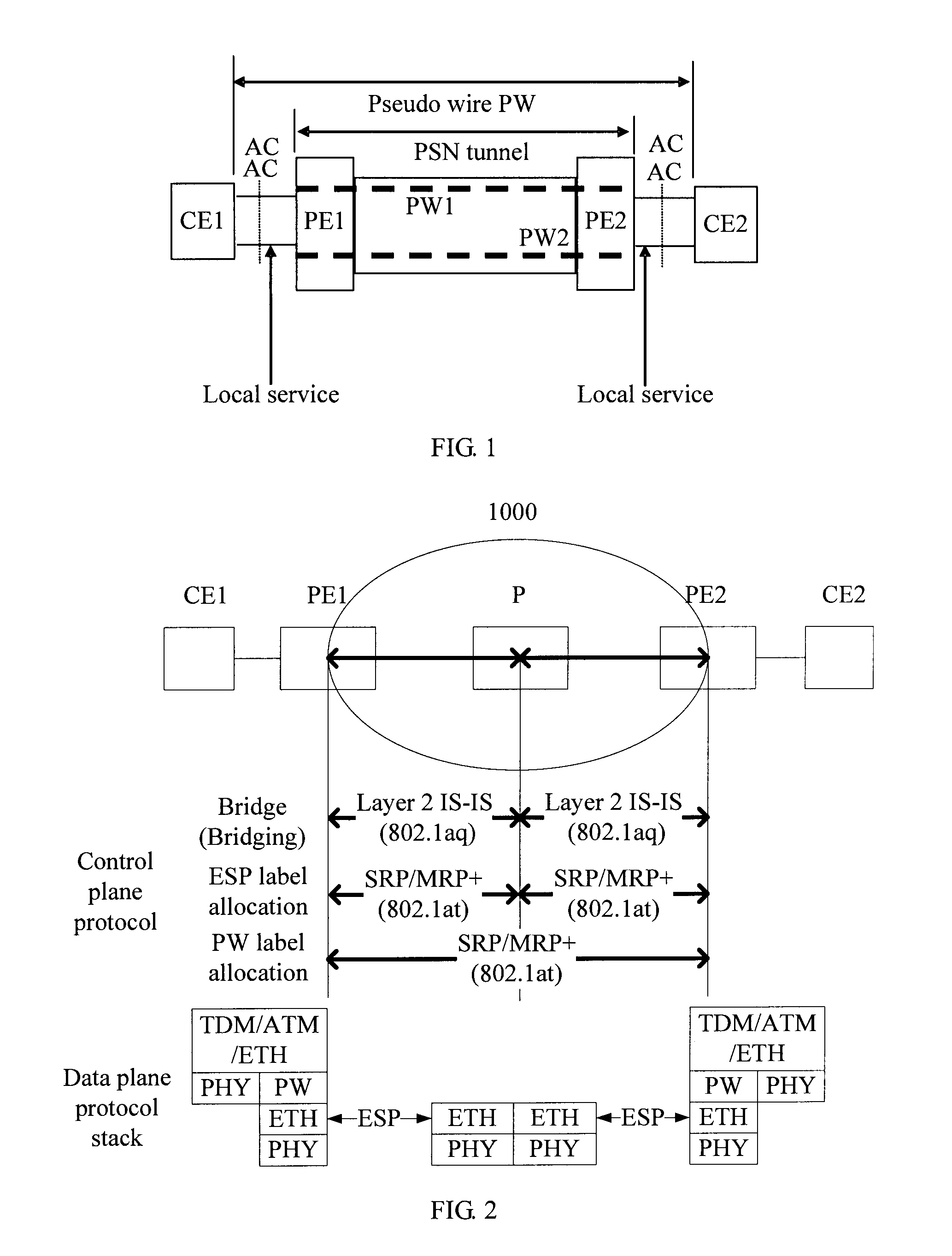
[0023]FIG. 2 is a schematic diagram of a communication network system that may apply an embodiment of the present invention. In FIG. 2, a communication network system 1000 includes provider edge devices PE1 (a source node device) and PE2 (a terminal node device), and a P (Provider, provider) node device (an intermediate node device). In the following, the PE1 and the PE2 are collectively referred to as a PE. The PE node device and the P node device both use a layer 2 device, such as a layer 2 Ethernet device. The provider edge devices PE1 and PE2 are connected to customer edge devices CE1 and CE2 respectively. FIG. 2 illustrates two customer edge devices, two provider edge devices and one ...


PUM


Abstract

A network communication method includes: allocating a pseudo wire (PW) label and/or an Ethernet (ETH) label through a layer 2 label allocation protocol; and performing data communication according to the allocated PW label and/or the allocated ETH label. According to the embodiments of the present invention, the label is allocated through the layer 2 label allocation protocol, thus maintaining the node device as a layer 2 device, meanwhile implementing label allocation, and reducing the complexity and improvement cost of network access.

Description

CROSS-REFERENCE TO RELATED APPLICATIONS[0001]This application is a continuation of International Application No. PCT / CN2010 / 077456, filed on Sep. 29, 2010, which claims priority to Chinese Patent Application No. 200910180739.4, filed on Oct. 21, 2009, both of which are hereby incorporated by reference in their entireties.FIELD OF THE INVENTION[0002]Embodiments of the present invention relate to the field of network communications, and in particular, to a network communication method and a network node device.BACKGROUND OF THE INVENTION[0003]A pseudo wire (Pseudo Wires, PW) is a mechanism for carrying a key element of an emulation service from one PE (Provider Edge, provider edge) device to another or multiple other PE devices through a PSN (Packet Switch Network, packet switch network). Through tunnels on the PSN network, such as an IP (Internet Protocol, Internet protocol), an L2TP (Layer 2 Tunneling Protocol, layer 2 tunneling protocol) or an MPLS (Multiprotocol Label Switching, m...

Claims


Application Information

Patent Timeline
IPC IPC(8): H04L12/56H04L45/50H04L45/02
CPCH04L12/4633H04L45/68H04L45/02H04L45/00H04L45/03
Inventor ZHENG, RUOBIN
Owner HUAWEI TECH CO LTD
Why Eureka
Try Eureka