System and method for load forecasting

a load forecasting and system technology, applied in the field of electric power grid, can solve the problems of time-consuming and labor-intensive load forecasting approaches, human intervention is difficult to quantify, and a certain amount of expertis

Active Publication Date: 2012-08-30
GENERAL ELECTRIC CO
View PDF10 Cites 34 Cited by
  • Summary
  • Abstract
  • Description
  • Claims
  • Application Information

AI Technical Summary

Problems solved by technology

Load forecasting approaches of this type which need human intervention can be time consuming.
F

Method used


Image

  • System and method for load forecasting
  • System and method for load forecasting
  • System and method for load forecasting

Examples


Embodiment Construction

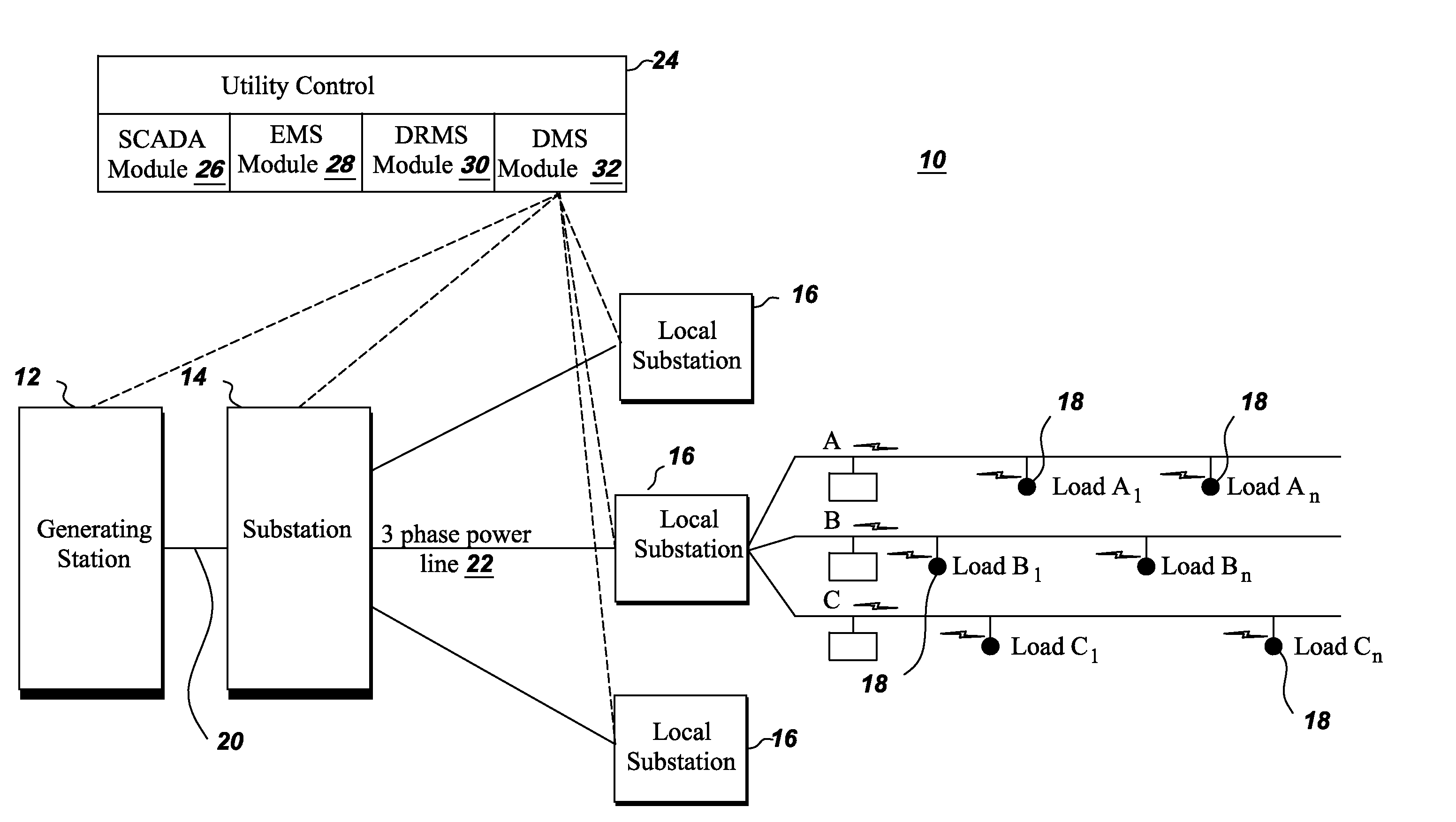
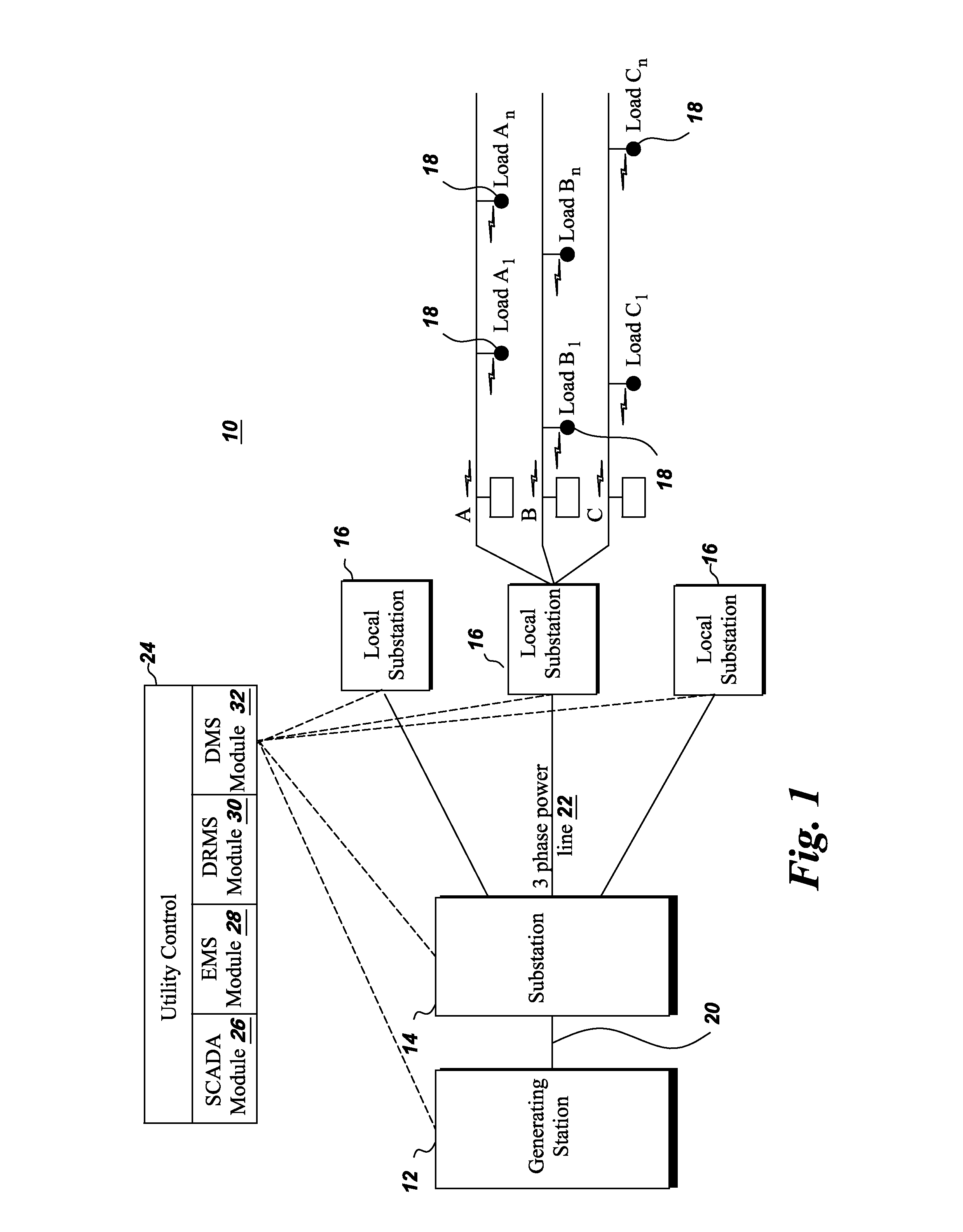
[0014]FIG. 1 illustrates a single line diagram of an overall electric system 10 from generation to utilization. The electric system 10 includes a generating station 12, a transmission substation 14, local substations or distribution substations 16 and loads 18. Generating station 12 may comprise a hydropower generating station, a thermal power generating station, a wind power generating station, or a solar power generating station, for example. Generating station 12 generates electricity at a generating station voltage which is in the range of 4 kV to 13 kV. The generating station voltage is stepped up to a higher transmission level voltage such as 110 kV and above by a generating station transformer (not shown) for more efficient transfer of the electricity.

[0015]The electricity at the transmission level voltage is transmitted to transmission substation 14 by primary transmission lines 20 that are configured to carry electricity long distances. At transmission substation 14, a redu...


PUM


Abstract

A method of load forecasting for a present day includes obtaining past observed load values of at least three earlier days and identifying a relationship between the present day's load forecast and the past observed load values including unknown weights associated with the past observed load values. The values of unknown weights are determined by comparing at least one previous day's load forecast with the observed load value of the at least one previous day. The determined weight values are then used in the relationship between the present day's load forecast and the past observed load values to forecast the present day's load.

Description

BACKGROUND[0001]The invention relates generally to an electric power grid and more specifically to load forecasting in the power grid.[0002]A smart grid delivers electricity to consumers while leveraging digital communication technology to reduce cost, save energy, and increase reliability. If designed properly, the smart grid will have a significant impact on improving a wide range of aspects in the electric power generation and distribution industry. Examples include self-healing, high-reliability, resistance to cyber attack, accommodation of a wide variety of types of distributed generation and storage mechanisms, optimized asset allocation, and minimization of operation and maintenance expenses as well as high-resolution market control that incorporates advanced metering and demand-response.[0003]Energy Management System (EMS) and Distribution Management System (DMS) are important components of the smart grid. EMS and DMS are utilized for providing capabilities to operate the bu...

Claims


Application Information

Patent Timeline
IPC IPC(8): G06F1/26
CPCH02J3/00H02J2003/003Y04S10/54G06Q50/06G06Q10/04H02J3/003Y04S10/50
Inventor KROK, MICHAEL JOSEPHPAN, YANREN, WEI
Owner GENERAL ELECTRIC CO
Why Eureka
Try Eureka