Method and device for displaying a three-dimensional view of the surface of a viewed object

a three-dimensional view and object technology, applied in the field of three-dimensional view of the surface of a viewed object, can solve the problems of inaccessibility to the surface, inability to view, and difficult to determine, and achieve the effect of improving detail and accurate inspection and measuremen

Active Publication Date: 2012-09-06
BAKER HUGHES INC
View PDF1 Cites 78 Cited by
  • Summary
  • Abstract
  • Description
  • Claims
  • Application Information

AI Technical Summary

Benefits of technology

[0007]A method and device for displaying a three-dimensional view of the surface of a viewed object is disclosed, wherein a subset of the three-dimensional data from the entire image of the viewed object in a region of interest is determined and displayed to provide enhanced detail in the region of interest. An advantage that may be realized in the practice of some disclosed embodiments of the method and device is more accurate inspections and measurements.

Problems solved by technology

In many instances, the surface is inaccessible and cannot be viewed without the use of the video inspection device.
In many instances, the contour of a viewed feature is difficult to assess from the two-dimensional image, making highly accurate placement of the cursors in the region of interest difficult.
For example, when trying to measure the depth of a dent or pit, it may be difficult to determine, from the two-dimensional image, the location of the deepest point in the pit or dent.
When the region of interest is relatively small in comparison to the full image of the surface, or when the region of interest is far from the origin of the field of view, the point cloud view of the full image is not always effective in providing the required level of detail of the region of interest.
In those instances, the point cloud view of the full image may lack sufficient detail and can become unwieldy as it is maneuvered about the origin of the field of view as the majority of three-dimensional data is irrelevant to the region of interest, which can be relatively far from the tip of the probe.
This colorized rendering of the point cloud view of the full image makes it difficult to inspect small details in the region of interest due to the large area and range covered by the entire view.

Method used


Image

  • Method and device for displaying a three-dimensional view of the surface of a viewed object
  • Method and device for displaying a three-dimensional view of the surface of a viewed object
  • Method and device for displaying a three-dimensional view of the surface of a viewed object

Examples


Embodiment Construction

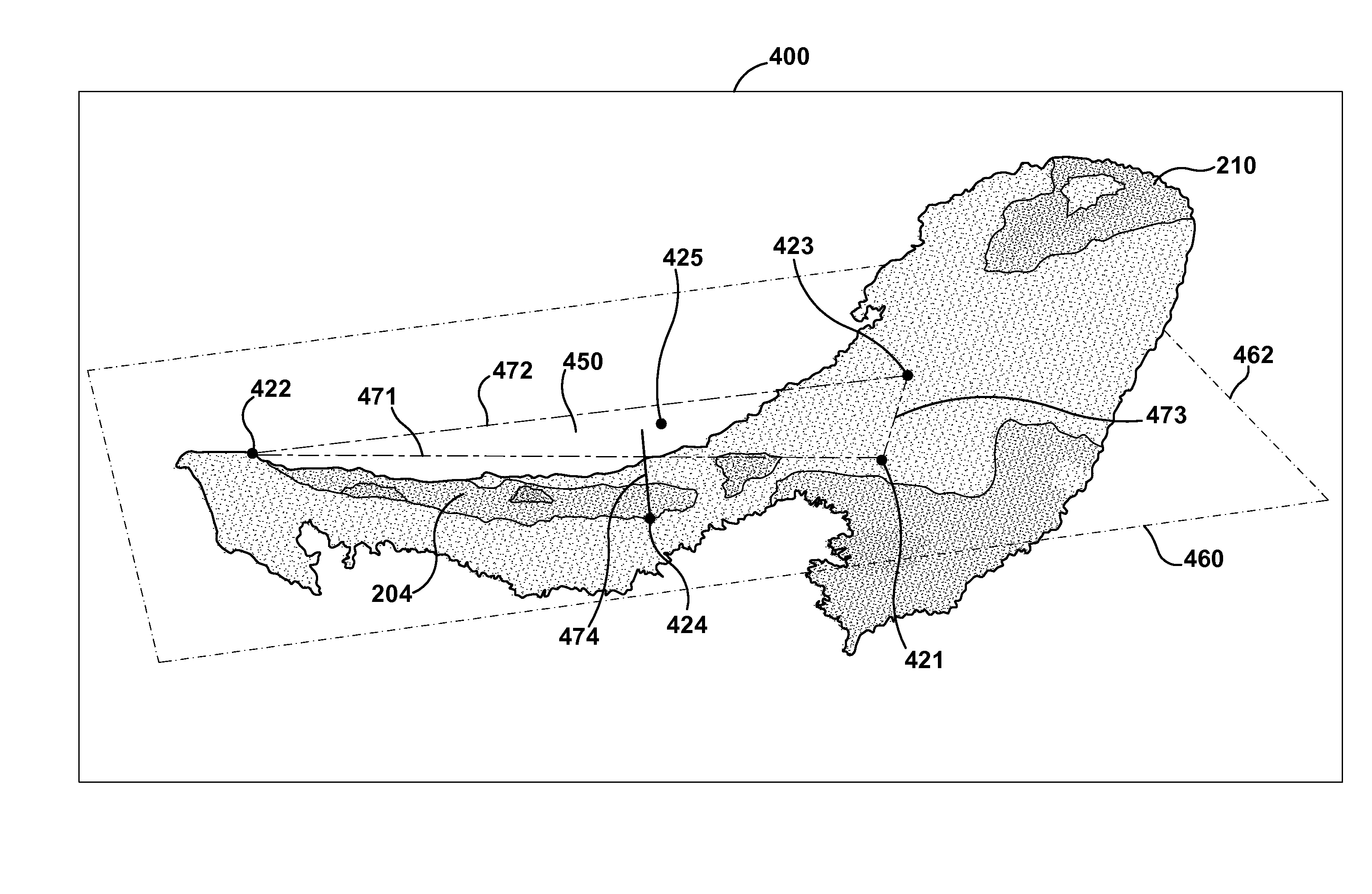
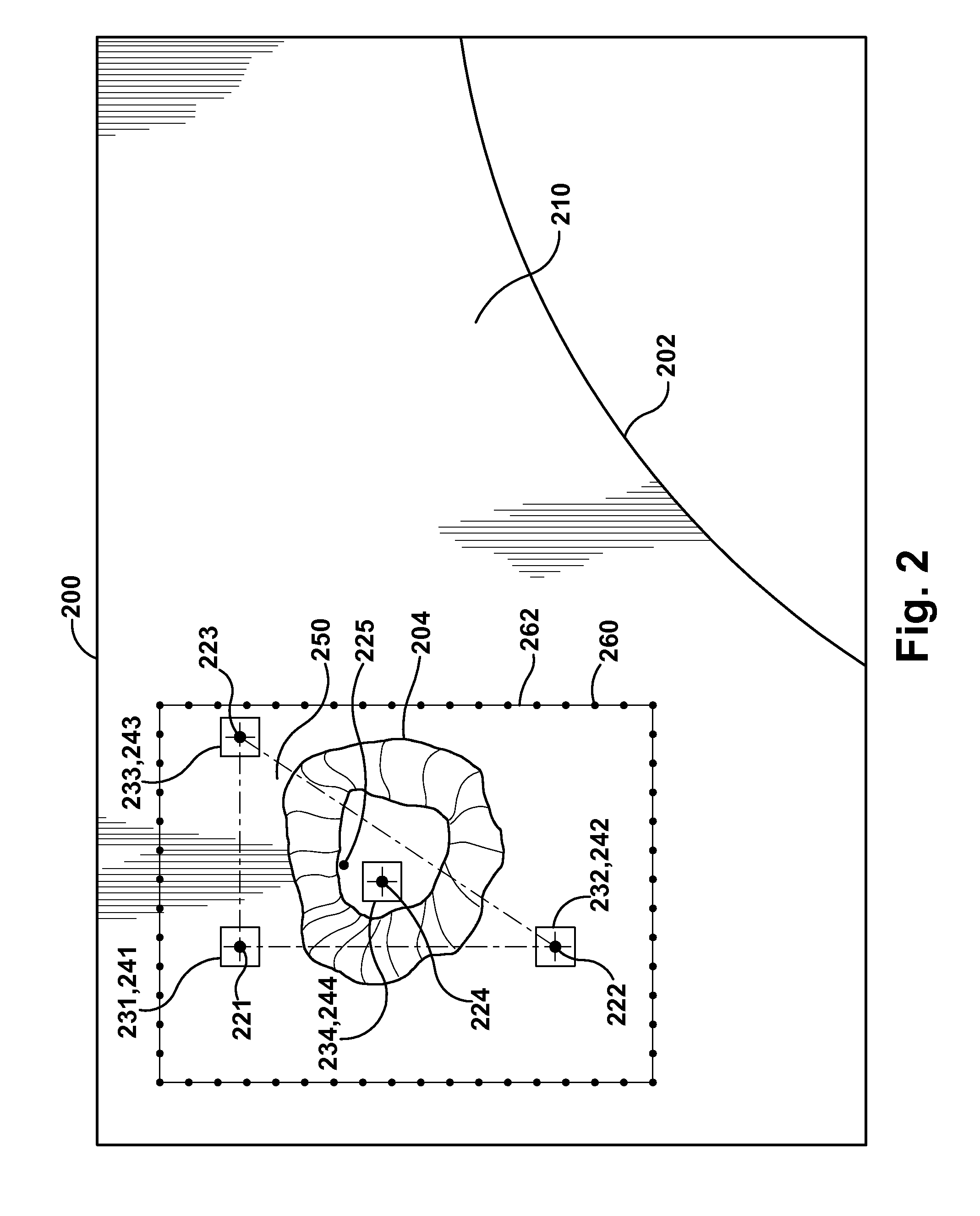
[0017]A method and device for displaying a three-dimensional view of the surface of a viewed object is disclosed, wherein a subset of the three-dimensional data from the entire image of the viewed object in a region of interest is determined and displayed to provide enhanced detail in the region of interest. An advantage that may be realized in the practice of some disclosed embodiments of the method and device is more accurate inspections and measurements.

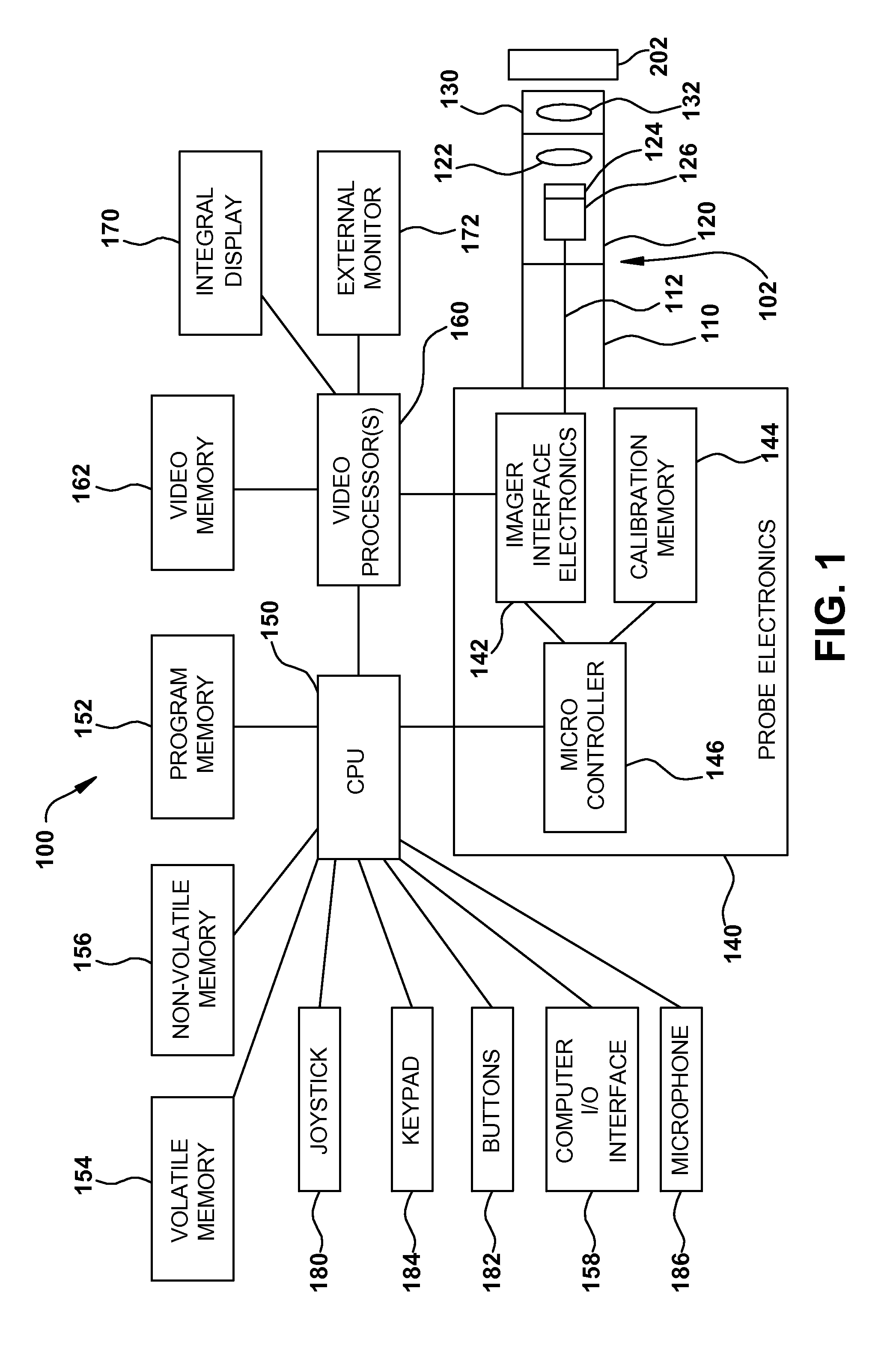
[0018]FIG. 1 is a block diagram of a video inspection device 100 in an exemplary embodiment of the invention. It will be understood that the video inspection device 100 shown in FIG. 1 is exemplary and that the scope of the invention is not limited to any particular video inspection device 100 or any particular configuration of components within a video inspection device 100.

[0019]Video inspection device 100 can include an elongated probe 102 comprising an insertion tube 110 and a head assembly 120 disposed at the distal end of th...


PUM


Abstract

A method and device for displaying a three-dimensional view of the surface of a viewed object is disclosed, wherein a subset of the three-dimensional data from the entire image of the viewed object in a region of interest is determined and displayed to provide enhanced detail in the region of interest.

Description

BACKGROUND OF THE INVENTION[0001]The subject matter disclosed herein relates to a method and device for displaying a three-dimensional view of the surface of a viewed object.[0002]Video inspection devices, such as video endoscopes, can be used to inspect the surface of a viewed object to identify and analyze irregularity on that surface that may have resulted from damage or wear of the object. In many instances, the surface is inaccessible and cannot be viewed without the use of the video inspection device. For example, a video endoscope can be used to inspect the surface of a blade of a turbine engine on an aircraft or power generation unit to identify any irregularities that may have formed on the surface to determine if any repair or further maintenance is required. In order to make that assessment, it is often necessary to obtain highly accurate dimensional measurements of the surface and the irregularity to verify that the irregularity does not exceed or fall outside an operati...

Claims


Application Information

Patent Timeline
Patent Type & Authority Applications(United States)
IPC IPC(8): G06T15/00
CPCG01B11/24G06T7/0002G06T2207/10068G06T2207/10028G06T7/602G06T7/62
Inventor BENDALL, CLARK ALEXANDER
Owner BAKER HUGHES INC
Why Eureka
Try Eureka