

Three-dimensional measurement method
- Summary
- Abstract
- Description
- Claims
- Application Information
AI Technical Summary
Benefits of technology
Problems solved by technology
Method used
Image

Examples
first embodiment
[0052]An embodiment of the present invention will be described with reference to the drawings.
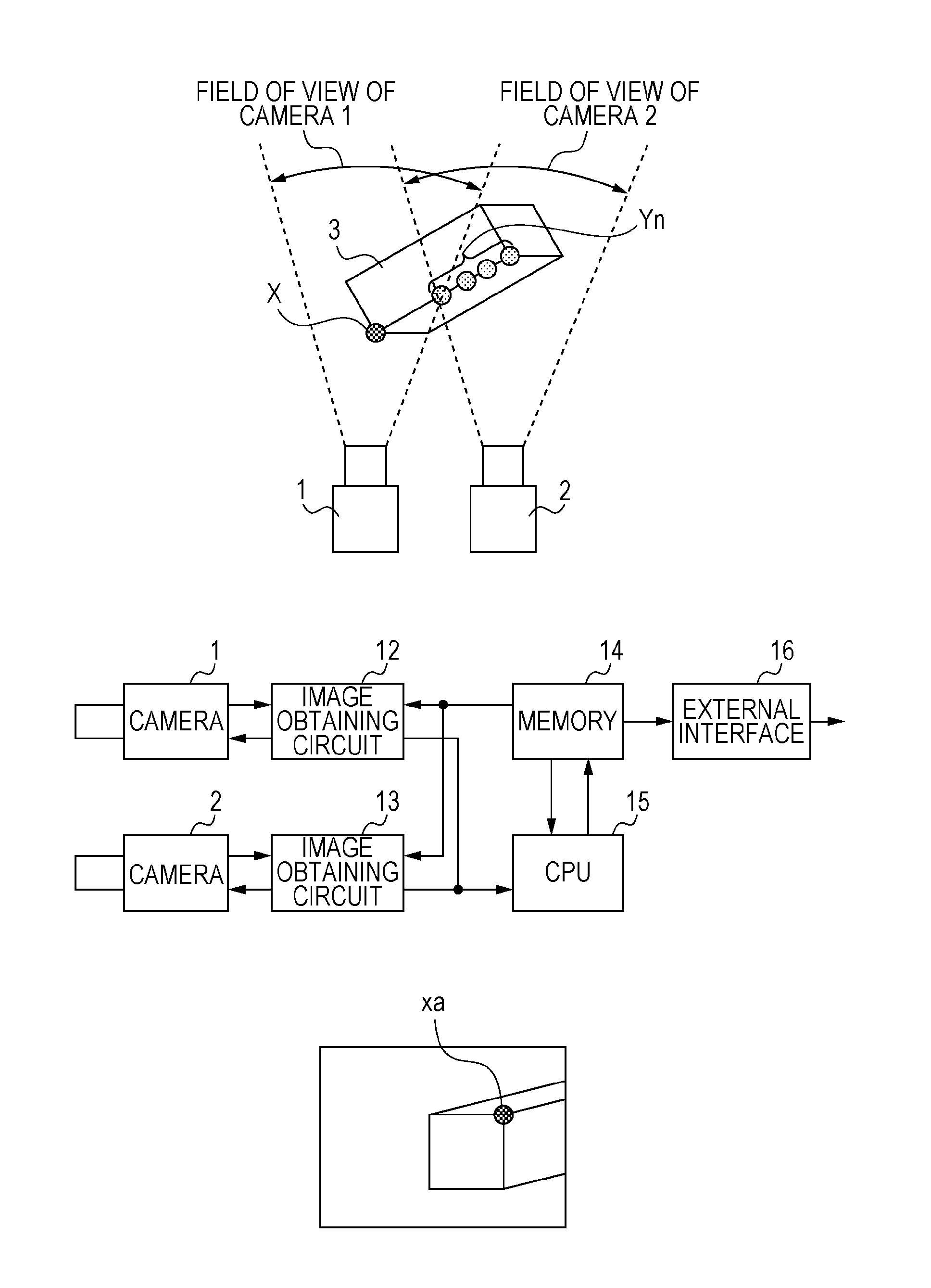
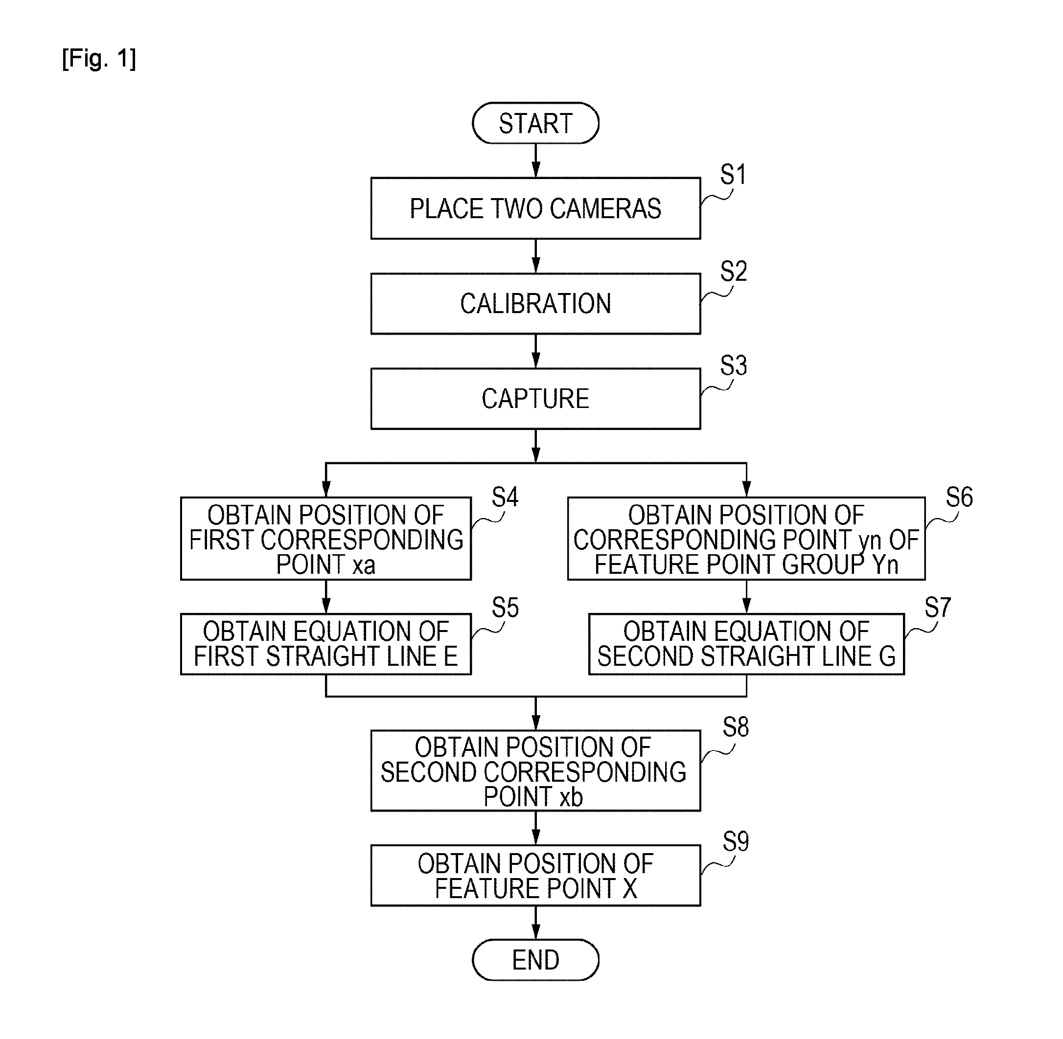
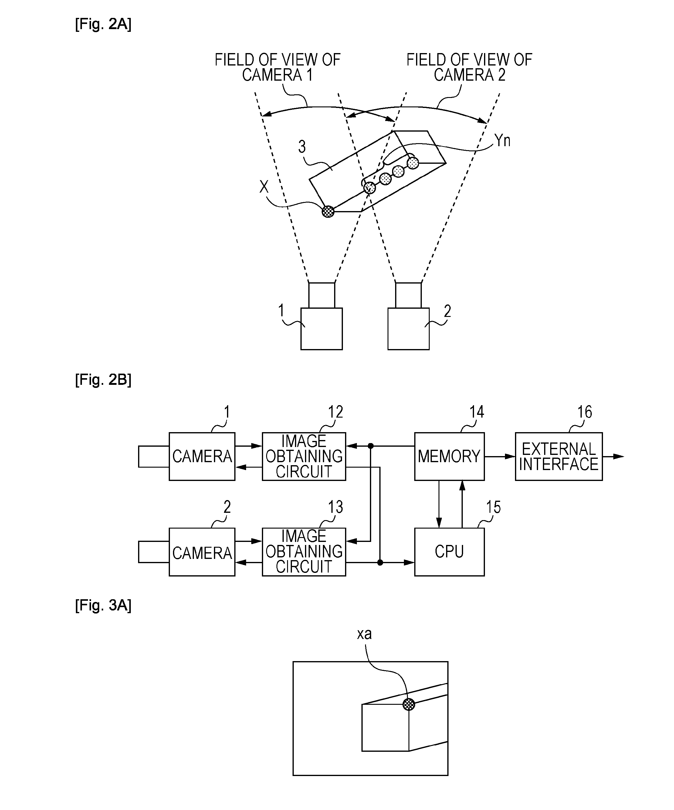
[0053]FIG. 1 is a flowchart illustrating a three-dimensional measurement method according to the present invention. FIG. 2A is a diagram illustrating a camera and a measurement target to be measured. FIG. 3A illustrates an image captured using a camera 1 illustrated in FIG. 2A, and FIG. 3B illustrates an image captured using a camera 2 illustrated in FIG. 2A.
[0054]Here, a point X illustrated in FIG. 2A is a point on a measurement target (product) 3 to be measured, and may be a point representing a feature of a three-dimensional object, such as a corner, an endpoint, or an intersection of the measurement target 3. A point representing a feature of a target to be measured three-dimensionally, such as the point X, is hereinafter referred to as a “feature point”. A plurality of feature points is referred to as a “feature point group”. A point xa is a point on an image captured using the camera ...
second embodiment
[0100]In the first embodiment, a feature point group continuous with a feature point to be measured is located on a straight line. The method described in the first embodiment may be performed if any other line (such as a curve) on an image corresponding to a feature point group Yn continuous with a feature point X is extrapolated using known information.
[0101]For example, as illustrated in FIG. 9, three-dimensional measurement of a feature point XX on a cylinder 4 will be discussed. A camera 1 is placed so that the feature point XX appears in an image captured using the camera 1, and a camera 2 is placed so that at least a feature point group YYn on the circular arc continuous with the feature point XX appears in an image captured using the camera 2.
[0102]Images captured using the cameras 1 and 2 under the set conditions are illustrated in FIGS. 10A and 10B, respectively. Here, xxa represents a corresponding point appearing in the image captured using the camera 1, which correspond...
third embodiment
[0111]FIG. 13 illustrates a third embodiment. A situation in which the three-dimensional position of an end En of a wall 5 is measured using a front camera 8 and a rear camera 7 mounted in a vehicle 6 is illustrated. A feature point En to be measured appears in an image captured using the front camera 8, and a feature point group Wn on the wall 5 continuous with the feature point En appears in an image captured using the rear camera 7. In the illustrated example, furthermore, there is no common field of view between the front camera 7 and the rear camera 8.
[0112]The image captured using the rear camera 7 may be an image on a sensor plane s7 illustrated in FIG. 14.
[0113]As in the first embodiment, a corresponding point Ena (not illustrated) corresponding to the end point En (feature point in this embodiment) of the wall 5 to be measured is determined from the image captured using the front camera 8. A straight line E8 in a plane S7 including the sensor plane s7 of the rear camera 7 i...
PUM
 Abstract
Description
Claims
Application Information