
Image capturing apparatus and control method therefor

a technology of image forming pixels and image signals, which is applied in the direction of instruments, television systems, color signal processing circuits, etc., can solve the problems of difficult to correct the pixel signal for forming part of an image is not obtained, and the image signal for focus detection is difficult to be corrected using nearby image forming pixels

Inactive Publication Date: 2012-09-06
CANON KK
View PDF6 Cites 8 Cited by
  • Summary
  • Abstract
  • Description
  • Claims
  • Application Information

AI Technical Summary

Benefits of technology

This solution allows for accurate focus detection even with defective focus detection pixels by correcting signals in parallel, preventing signal imbalance and maintaining focus detection accuracy.

Problems solved by technology

Although pixel signals for focus detection are obtained from the focus detection pixels, pixel signals for forming part of an image are not obtained.
However, in a case in which defects in the manufacturing process of the image sensor such as white defects and black defects are present in the focus detection pixels, it is difficult to correct the pixel signals for focus detection obtained from the focus detection pixels using the image signals of pixels around the focus detection pixels.
As a result, in a case in which the focus detection pixels are configured as divided-pupil pixels, when there is a defect in the focus detection pixels it is difficult to correct the image signals for focus detection using nearby image forming pixels.

Method used


Image

  • Image capturing apparatus and control method therefor
  • Image capturing apparatus and control method therefor
  • Image capturing apparatus and control method therefor

Examples


first embodiment

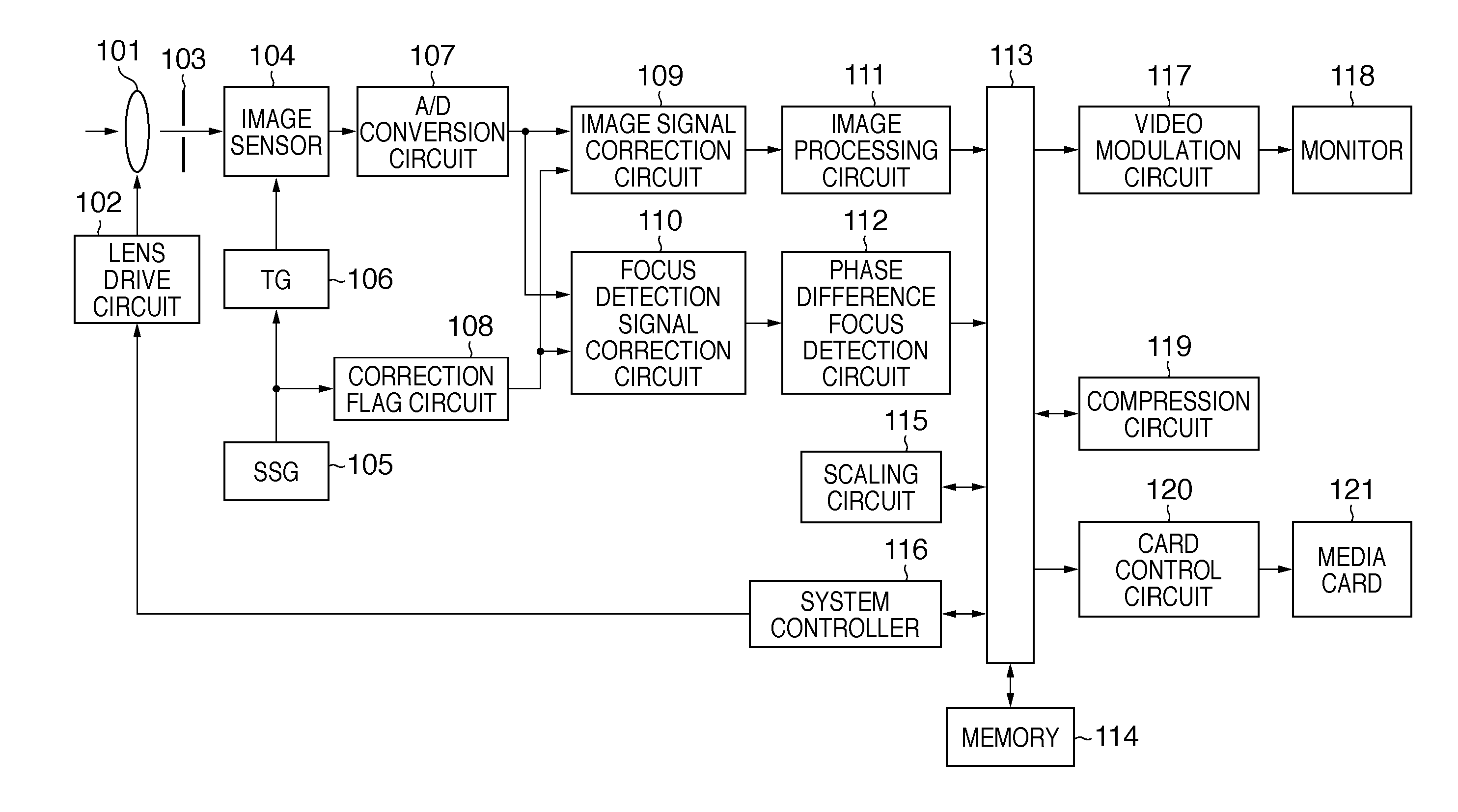
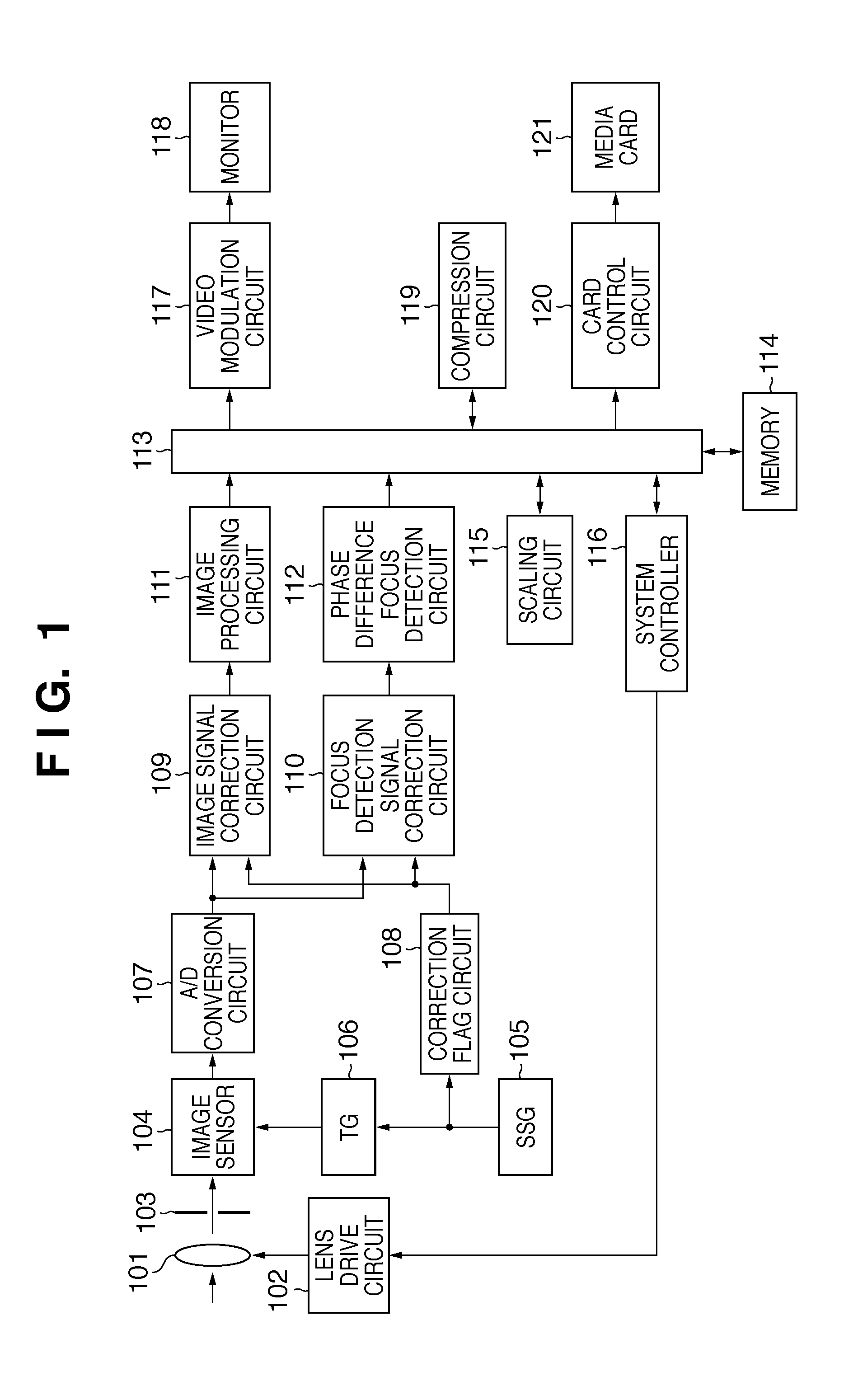
[0034]FIG. 1 is a block diagram showing the circuit configuration of an image capturing apparatus according to a preferred first embodiment of the present invention. Reference numeral 101 designates a plurality of image sensing lenses, and 102 designates a lens drive circuit for driving the image sensing lenses 101. Reference numeral 103 designates an aperture for adjusting exposure. Reference numeral 104 designates an image sensor, in which pixels comprising photoelectric converter elements that photoelectrically convert incident light are arranged in two dimensions, with at least some of the pixels configured as focus detection pixels for focus detection. Reference numeral 105 designates a synchronization signal generator (hereinafter “SSG”) that generates a horizontal synchronization signal HD and a vertical synchronization signal VD of set cycles. Reference numeral 106 designates a timing generator (hereinafter “TG”) that generates a control signal that drives the image sensor 1...

second embodiment

[0065]FIG. 9 is a circuit configuration diagram of an image capturing apparatus according to a preferred second embodiment of the present invention. A description of an image capture operation performed by the circuit shown in FIG. 9 follows. It is to be noted that the same reference numerals are provided for those elements of the configuration that are the same as those shown in FIG. 1 and a description thereof is omitted. In addition, FIG. 16 is a flow chart showing the procedure for a correction process of the second embodiment, and the description proceeds while referring thereto as convenient. Processes that are the same as those shown in FIG. 15 are given the same step numbers.

[0066]As with the first embodiment, light entering from the image sensing lenses 101 is photoelectrically converted into electrical signals at the image sensor 104 and then converted into digital image data at the A / D conversion circuit 107.

[0067]A correction flag circuit 1008 operates a spot flag, a foc...


PUM


Abstract

An image capturing apparatus includes an image sensor 104 in which at least part of pixels arranged in two dimensions are configured as focus detection pixels with divided-pupil, a memory control circuit 113 configured to read out from a memory position information for the focus detection pixels 401, 402 stored in the memory, and a correction circuit 110 configured to identify positions of the focus detection pixels 401, 402 in the image sensor 104 based on the position information for the focus detection pixels 401, 402 and to correct a defective focus detection pixel signal using defect-free focus detection pixel signals.

Description

CROSS-REFERENCE TO RELATED APPLICATION[0001]This application is a continuation of application Ser. No. 12 / 739,234, filed Apr. 22, 2010; which was the National Stage application under 35 U.S.C. 371 of International Application No. PCT / JP / 2008 / 072719, filed Dec. 8, 2008, the entire disclosures of which are hereby incorporated by reference.TECHNICAL FIELD[0002]The present invention relates to an image capturing apparatus and a control method therefor, and more particularly, to an image capturing apparatus that uses focus evaluation pixels to perform focus detection and a control method for such image capturing apparatus.BACKGROUND ART[0003]With recent advances in the sophistication of the image sensors with which image capturing apparatuses such as digital still cameras and the like are equipped, performing high-speed, high-accuracy image processing has become more important than ever. At the same time, conventionally, a method of performing autofocus (hereinafter “focus detection”) qu...

Claims


Application Information

Patent Timeline
Patent Type & Authority Applications(United States)
IPC IPC(8): H04N5/225H04N23/40G02B7/28G02B7/34H04N25/00H04N101/00
CPCG03B13/36H04N5/23212H04N5/378H04N5/3696H04N5/367H04N23/672H04N25/68H04N25/704H04N25/134H04N25/75
Inventor HODA, SAORIRENGAKUJI, HIDEYUKIHOMMA, YOSHIHIRO
Owner CANON KK
Features
  • Generate Ideas
  • Intellectual Property
  • Life Sciences
  • Materials
  • Tech Scout
  • Unparalleled Data Quality
  • Higher Quality Content
  • 60% Fewer Hallucinations
Learn More