
Light Engine Using Common Building Blocks

a technology of light engine and common building blocks, applied in the field of multi-prism system, can solve the problems of large number of known mirror systems, large number of led dice, and difficulty in optimum positioning of led dice in individual led di

Inactive Publication Date: 2012-09-06
FORD GLOBAL TECH LLC
View PDF1 Cites 4 Cited by
  • Summary
  • Abstract
  • Description
  • Claims
  • Application Information

AI Technical Summary

Problems solved by technology

Light engines using red, green, and blue light emitting diodes (LEDs) on a single common substrate generally suffer from efficiency and / or color uniformity problems.
For example, the individual LED dice may be difficult to locate in an optimum position relative to the collimating optics.
Known mirror systems are large and expensive, and it has not been possible to efficiently integrate them in a compact, low-cost light engine.

Method used


Image

  • Light Engine Using Common Building Blocks
  • Light Engine Using Common Building Blocks
  • Light Engine Using Common Building Blocks

Examples


Embodiment Construction

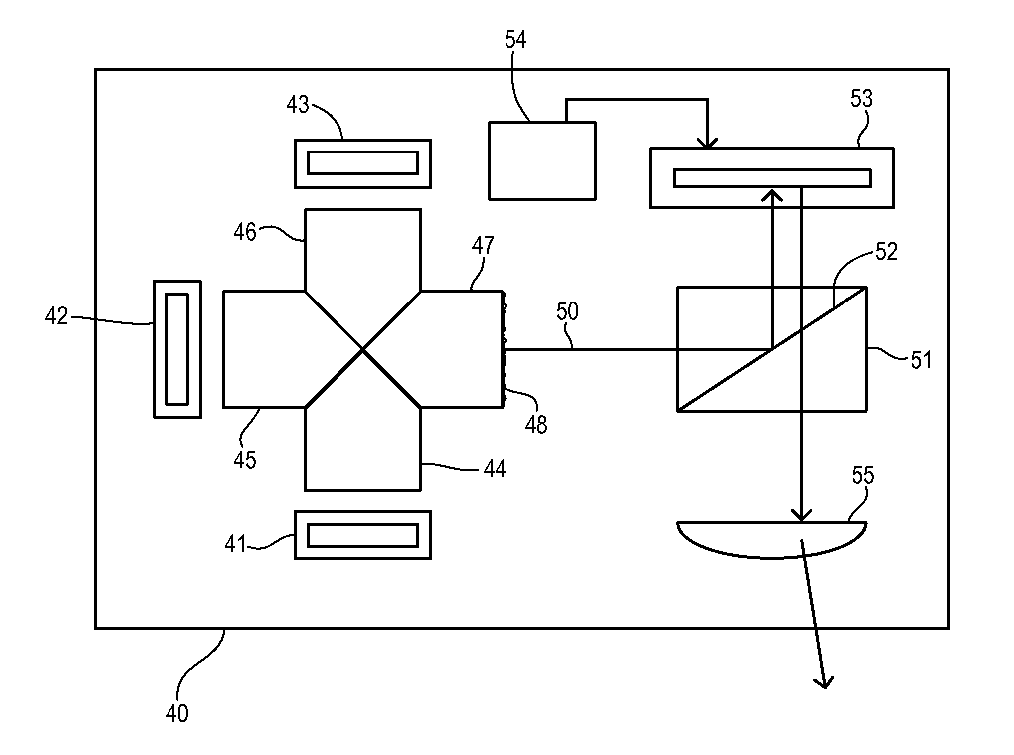
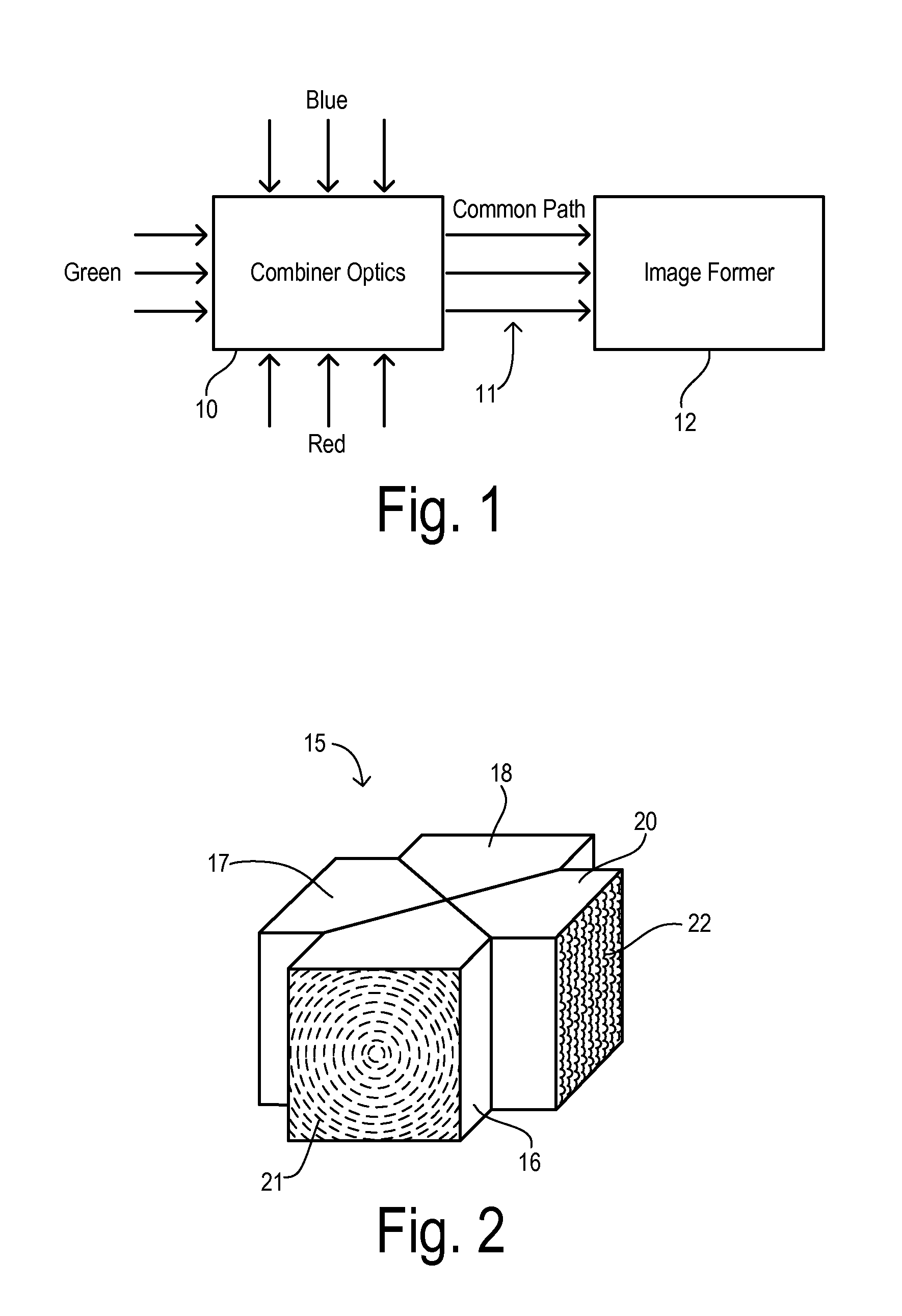
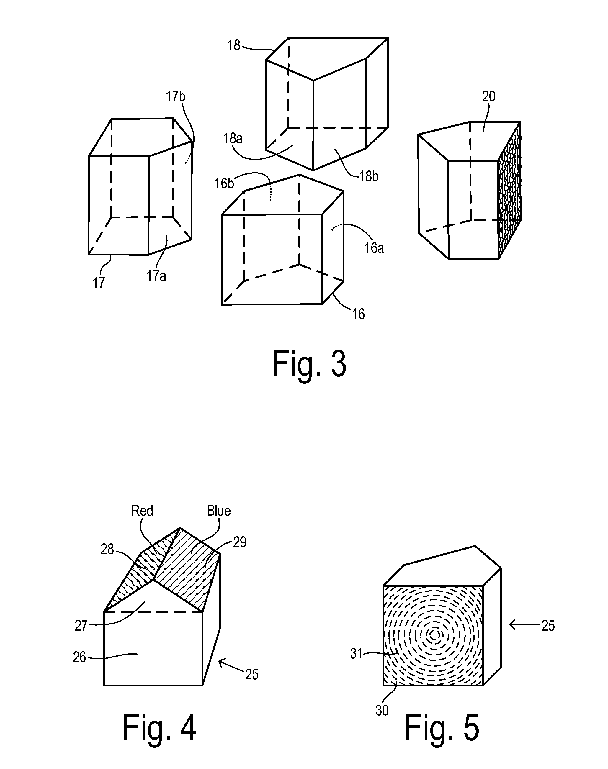
[0017]The present invention uses a combination of micro-optics, molded plastic light guides, and dichroic surfaces or coatings to deliver a compact, low-cost, efficient light engine. In one embodiment, separate red, green, and blue LEDs with Lambertian emission patterns are used as the sources for red, green, and blue light. Light from each LED is collimated in a separate molded plastic part with a micro-optic collimation pattern on the side closest to the LED. Prism surfaces on the other side of the plastic part have an optimum reflection angle and are provided with dichroic surfaces having transmission and reflection properties tailored to the colors from the LED light sources. These prism elements are brought together with a collector / diffuser element which is also a molded plastic part and has an optical micro-structure molded into the part for diffusing an exiting light beam to a desired f-number.

[0018]By appropriately selecting the dichroic properties and the arrangement of th...


PUM


Abstract

A light engine combines light of first, second, and third color ranges using three pentagonal prism elements. Each prism has first and second diagonal surfaces. Each first diagonal surface has a first dichroic treatment and each second diagonal surface has a second dichroic treatment. The prisms are arranged with the first diagonal surface of the first prism juxtaposed with one diagonal surface of the third prism and with the second diagonal surface of the second prism juxtaposed with the other diagonal surface of the third prism. A first light beam of the first color is reflected at a right angle by the first diagonal surfaces, and a second light beam is reflected at a right angle by the second diagonal surfaces. A third light beam of the third color passes unreflected through the surfaces to produce a combined light beam or common output light path.

Description

CROSS REFERENCE TO RELATED APPLICATIONS[0001]Not Applicable.STATEMENT REGARDING FEDERALLY SPONSORED RESEARCH[0002]Not Applicable.BACKGROUND OF THE INVENTION[0003]The present invention relates in general to a light combiner for image projection systems, and, more specifically, to a multi-prism system for directing colored light sources along a common output light path.[0004]Various types of video projection systems are in common use today. An imaging device such as a Digital Light Processor (DLP) or Liquid Crystal on Silicon (LCOS) device are illuminated by and selectably modify light according to an instantaneous frame of a video image. To keep the size, weight, and cost of such projectors to such a minimum, the video projection system usually uses only a single imaging device while producing a color image. The device is sequentially illuminated with red, green, and blue portions of the image. This mode of operation is called field-sequential color. The illumination source or light ...

Claims


Application Information

Patent Timeline
IPC IPC(8): G03B21/28
CPCG02B5/021G02B5/04G02B27/1053G03B21/2066G03B11/00G03B21/2013G02B27/126
Inventor DASSANAYAKE, MAHENDRA S.BILGER, DONALD P.
Owner FORD GLOBAL TECH LLC
Learn More