Interspinous spacer implant

a spacer implant and implant technology, applied in the field of interspinous spacer implants, can solve the problems of limiting the access to the pars and transverse processes, unsatisfactory decortication, and large amount of blood loss, and achieve the effect of stabilizing vertebrae and promoting bone growth

Active Publication Date: 2012-09-06
KIC VENTURES LLC
View PDF2 Cites 45 Cited by
  • Summary
  • Abstract
  • Description
  • Claims
  • Application Information

AI Technical Summary

Benefits of technology

[0011]Among the advantages of this invention may be one or more of the following. The assembly stabilizes vertebrae by attaching components to the spinous processes of the vertebrae. This stabilization device does not add bulk to the lateral aspect of the spine and does not limit access to the pars and transverse processes for decortication and placement of bone graft. The compact form of the implant assembly allows it to be implanted via mini-open surgery. The device's shape conforms to the local vertebral anatomy. In particular, the adjustable plates and spacers fit to the spinous process contour. The device may be used alone or as and adjunct to facet or pedicle screw systems. It provides multi-level (i.e., multi-vertebra) fusion through replication of the basic unit. The device is securely attached to the spinous processes via the center post, individual components, and pins. The allograft spacer promotes bone growth. The interspinous spacer may be inserted laterally from the side or from the front.

Problems solved by technology

Both the component systems and the rod systems add bulk along the lateral aspect of the spine and limit access to the pars and transverse processes for decortication and placement of bone graft.
However, decortication is not always desirable because it increases the amount of blood loss and makes it more difficult to maintain a clear operative field.
However, the rod fixation system is difficult to extend to higher or lower levels that need to be fused.
Although there are connectors and techniques to lengthen the fixation via rods, they tend to be complex, difficult to use, and time consuming.

Method used


Image

  • Interspinous spacer implant
  • Interspinous spacer implant
  • Interspinous spacer implant

Examples


Embodiment Construction

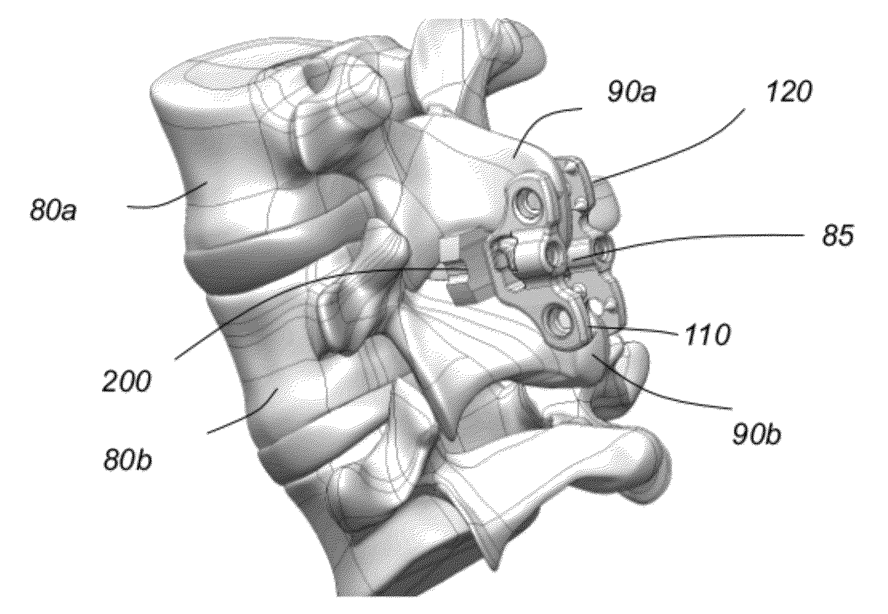
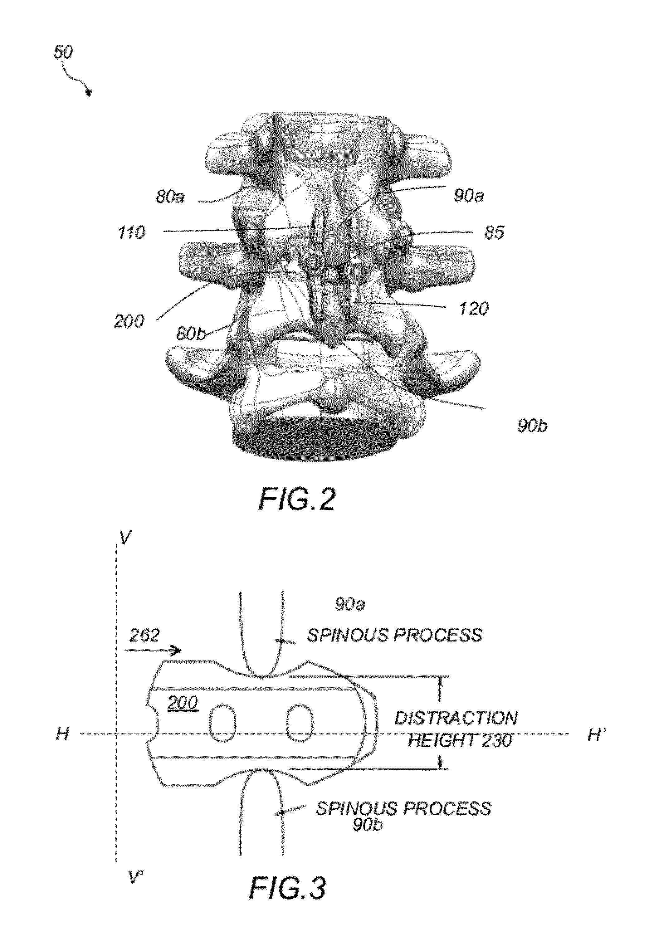
[0043]The present invention relates to a system and a method for an improved spinous process fixation implant assembly 50, shown in FIG. 2. The spinous process fixation implant assembly 50 includes a spinous process fixation implant 100 and an interspinous spacer implant 200. The spinous process fixation implant 100 includes elongated first and second components 110, 120, that are arranged opposite and parallel to each other. First and second spinous processes 90a, 90b of first and second adjacent vertebrae 80a, 80b are clamped between the first and second components 110, 120, respectively, and are separated by the interspinous spacer implant 200, as shown in FIG. 2 and FIG. 3.

[0044]Referring to FIG. 4A-4C, spinous process fixation implant 100 includes first elongated component 110, second elongated component 120, top and bottom pins, 180a, 180b, and set screws 140a, 140b. First component 110 includes an elongated body 112 and one integral post 170a. Elongated body 112 has an essent...


PUM

PropertyMeasurementUnit
widthaaaaaaaaaa
widthaaaaaaaaaa
thicknessaaaaaaaaaa

Abstract

An improved spinous process fixation implant assembly 50 includes a spinous process fixation implant 100 and an interspinous spacer implant 200. The spinous process fixation implant 100 includes elongated first and second components 110, 120, that are arranged opposite and parallel to each other. First and second spinous processes 90a, 90b of first and second adjacent vertebrae 80a, 80b are clamped between the first and second components 110, 120, respectively, and are separated by the interspinous spacer implant 200. The interspinous spacer implant 200 may be inserted between the spinous processes of adjacent vertebrae from two different directions.

Description

CROSS REFERENCE TO RELATED CO-PENDING APPLICATIONS[0001]This application claims the benefit of U.S. provisional application Ser. No. 61 / 449,274 filed Mar. 4, 2011 and entitled “INTERSPINOUS SPACER IMPLANT”, the contents of which are expressly incorporated herein by reference.[0002]This application is also a continuation in part of U.S. application Ser. No. 13 / 182,525 filed Jul. 14, 2011 “INTERSPINOUS FIXATION IMPLANT”, the contents of which are expressly incorporated herein by reference.FIELD OF THE INVENTION[0003]The present invention relates to an interspinous spacer implant, and more particularly, to an interspinous spacer implant that is inserted between the spinous processes of adjacent vertebrae from two different directions.BACKGROUND OF THE INVENTION[0004]The human spine is comprised of individual vertebrae 30 that are connected to each other to form a spinal column 29, shown in FIG. 1A. Referring to FIGS. 1B and 1C, each vertebra 30 has a cylindrical bony body (vertebral bo...

Claims


Application Information

Patent Timeline
Patent Type & Authority Applications(United States)
IPC IPC(8): A61B17/70A61B17/88
CPCA61F2/3094A61B17/32053A61F2/4611A61F2002/2817A61F2002/2835A61F2002/30777A61F2002/30785A61F2002/3082A61F2002/30841A61F2002/3085A61F2002/30909A61F2002/4475A61F2002/448A61F2310/00017A61F2310/00023A61F2310/00029A61F2310/00293A61F2310/00329A61F2310/00365A61L27/425A61F2/30965A61B2019/461A61B2017/0256A61B17/7068A61B17/1659A61B17/1671A61B17/7062A61L27/06A61L27/042A61L27/04A61B2090/061A61F2002/30593A61B17/7065A61B17/7067
Inventor CHIN, KINGSLEY R.IBARRA, MATTHEWHENSHAW, CRAIGDRNEK, MICHAELSEARS, CHARLES
Owner KIC VENTURES LLC
Why Eureka
Try Eureka