
Lock

a technology of locking device and container, which is applied in the field of locks, can solve the problems of lack of accountability, devices that do not offer assistance in determining when and where the intrusion might have occurred, and limit themselves to physically locking containers, etc., and achieves the effect of simple operation and resistance to tampering

Inactive Publication Date: 2012-09-13
SECURITY ENHANCEMENT SYST
View PDF32 Cites 26 Cited by
  • Summary
  • Abstract
  • Description
  • Claims
  • Application Information

AI Technical Summary

Benefits of technology

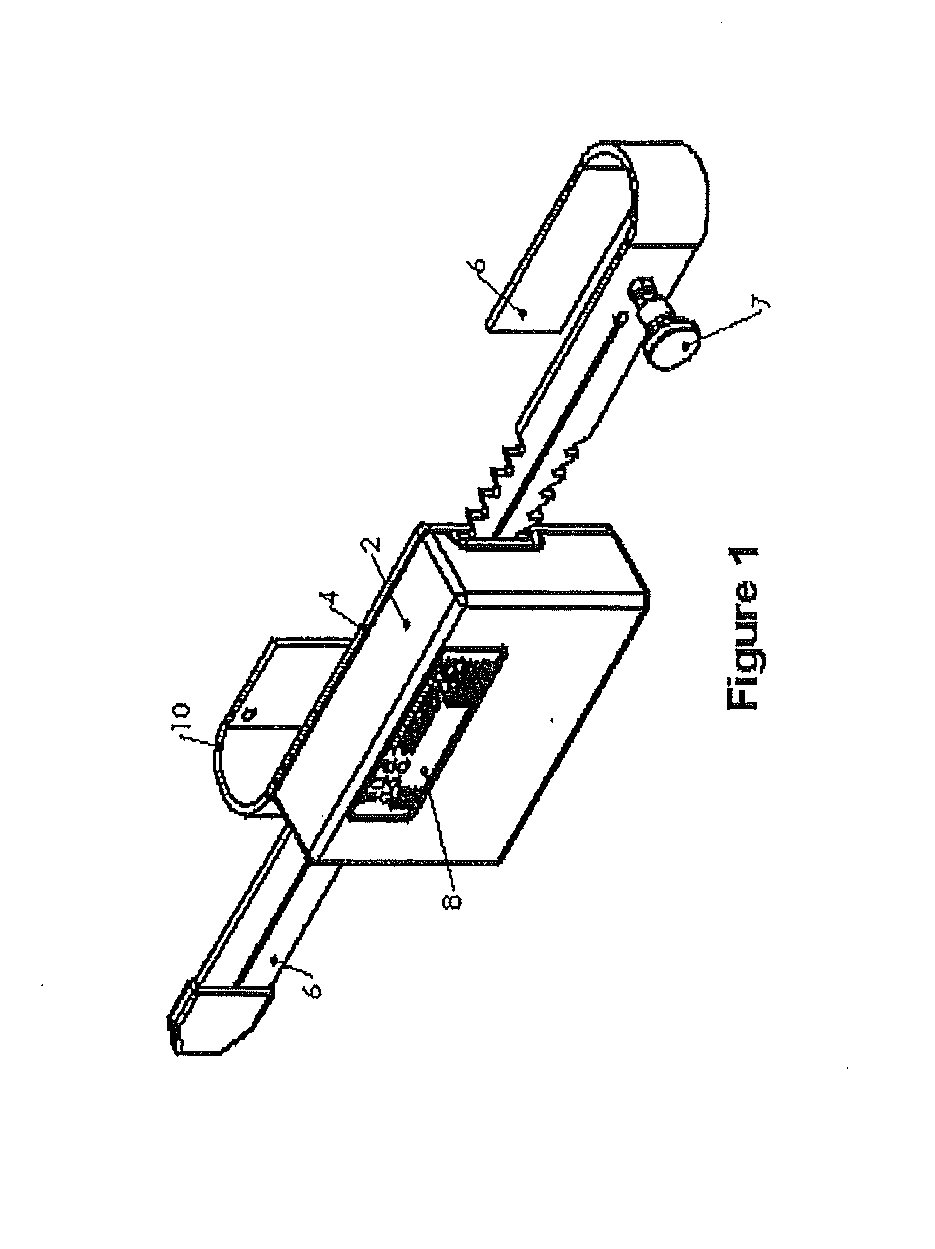
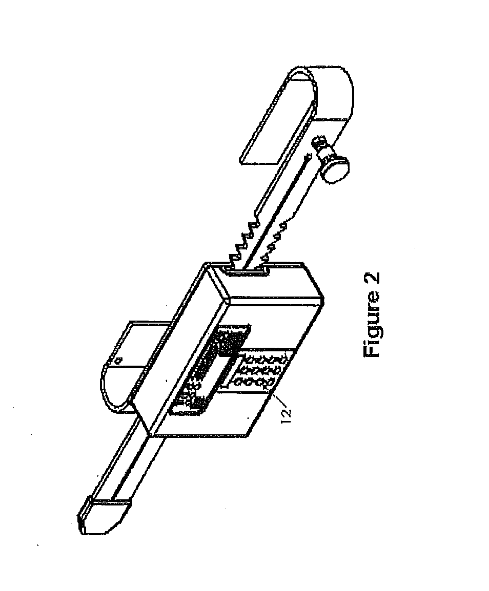
[0010]The present invention is a re-usable, electro-mechanical, event-logging lock for cargo containers or similar enclosed spaces such as storage units. The robust locking mechanism includes a dual ratcheting cam, which firmly secures doors of a container or other enclosure. The lock continuously monitors lock status and detects tampering. The lock logs all operation and tampering events with a date and time stamp. The device is rugged, simple to operate, resistant to tampering, and will endure shock, rough handling and extreme weather conditions.

Problems solved by technology

Besides thieves who break into random cargo containers, there have been instances where the driver responsible for the cargo is directly involved in the robbery.
Locking devices and technologies currently available in the market limit themselves to physically locking the containers.
The biggest disadvantage in this case is the lack of accountability in the event of theft.
These devices offer no assistance in determining when and where the intrusion might have occurred.
All of the cut bolts are either wasted or are recycled, which involves additional handling and shipping expenses.
Other reusable locks available come with a recurring expense of bolt-seal for each use.
When cargo theft occurs on such a complex route involving multiple individuals and shipping companies and if no proof exists as to when the theft occurred, it becomes extremely difficult for the insurance companies to determine financial responsibility.
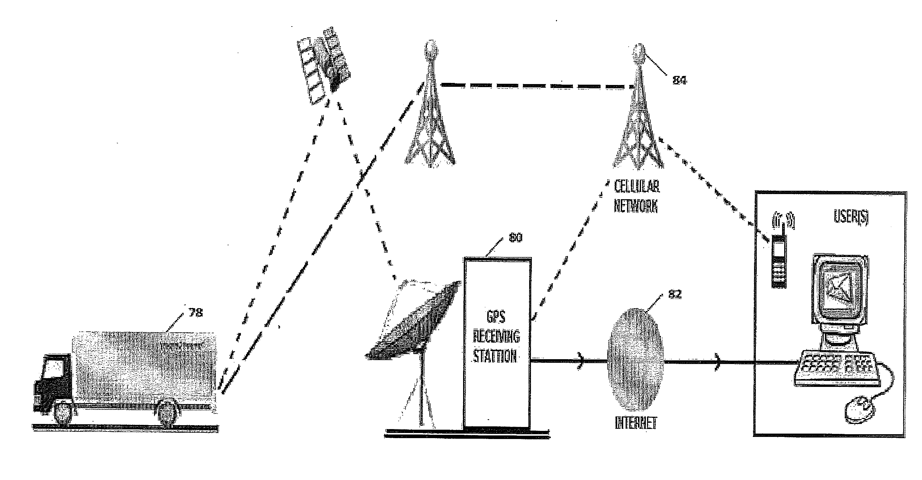
Besides cargo theft, containers have also been targeted to smuggle illegal goods and people.
US Customs and Border Protection (CBP) uses expensive technologies like X-ray, to deter these illegal activities.

Method used


Image

  • Lock
  • Lock
  • Lock

Examples


Embodiment Construction

[0027]A preferred embodiment provides a secure locking mechanism which can be used with shipping containers, including ISO styled cargo containers. Cargo container doors typically have vertical keeper bars, which are generally parallel bars, permanently attached to the doors of the container to secure the doors in the closed position during transit or storage. In a preferred embodiment, the device is constructed and arranged to be installed on the keeper bars. Once the embodiment is properly installed on keeper bars and locked, access to the container is prohibited. An alternate embodiment may be permanently installed on the interior of the container, such as the doors, or similar enclosure.

[0028]FIG. 1 shows a preferred embodiment of the invention when fully assembled. Front cover assembly 2, back plate assembly 4, and locking bar assembly 6 are the three major sub-assemblies involved. The locking bar 6, which may be a J-shaped bar, or referred to as a J-bar, is inserted by slidabl...


PUM


Abstract

An electro-mechanical lock for cargo containers or similar enclosed spaces such as storage units. The locking mechanism includes a dual-ratcheting mechanism, which is normally in the locked position, and which firmly secures doors of a container or other enclosure. To unlock the device, the user obtains a temporary access code and unlocks the device, either by a wireless interface or by, for example, a key pad. The device incorporates a rolling access code algorithm that changes the access code based upon a pre-defined customer selected time period during which the code is valid. Once the validity period expires the user must obtain a new access code from a secure access code source to unlock the device. When access is desired, the user contacts a remote secure access code source, which provides the access code for the associated lock and time period.

Description

[0001]This application is a continuation-in-part of U.S. patent application Ser. No. 13 / 414,348 filed Mar. 7, 2012, which claimed the benefit of U.S. Provisional Application Ser. No. 61 / 450,185 filed Mar. 8, 2011, the benefit of which is claimed herein.BACKGROUND OF THE INVENTION[0002]Intermodal security is a major concern for all businesses that need to ship material goods via truck, rail and sea.[0003]According to a recent report released by Federal Bureau of Investigation (FBI), industry experts estimate all cargo theft adds up to $30 billion each year. Besides thieves who break into random cargo containers, there have been instances where the driver responsible for the cargo is directly involved in the robbery. The FBI has also identified this and has attributed an offense code to ‘driver involved cargo theft’ in its Uniform Crime Report (UCR).[0004]Locking devices and technologies currently available in the market limit themselves to physically locking the containers. Most of t...

Claims


Application Information

Patent Timeline
Patent Type & Authority Applications(United States)
IPC IPC(8): E05B47/02
CPCE05B39/005E05B41/00G01S19/39E05C19/186E05B2047/0095Y10T70/7062
Inventor UFKES, PHILIP J.
Owner SECURITY ENHANCEMENT SYST
Learn More