Method for collecting liquid surface residual film, method for transferring liquid pressure using same, collection device therefor, and liquid pressure transfer device using same

a liquid surface residual film and collection method technology, applied in the direction of water supply installation, cleaning using liquids, container discharge methods, etc., can solve the problems of high environmental impact, increase the overall cost of liquid pressure transfer, and long time, so as to achieve quick and reliable collection, easy maintenance of the entire apparatus, and low chance of adverse effects on the transfer film at the transfer position

Active Publication Date: 2012-09-13
TAICA
View PDF4 Cites 5 Cited by
  • Summary
  • Abstract
  • Description
  • Claims
  • Application Information

AI Technical Summary

Benefits of technology

[0054]The constitution of the invention described in each claim is used as means for solving the above problems.
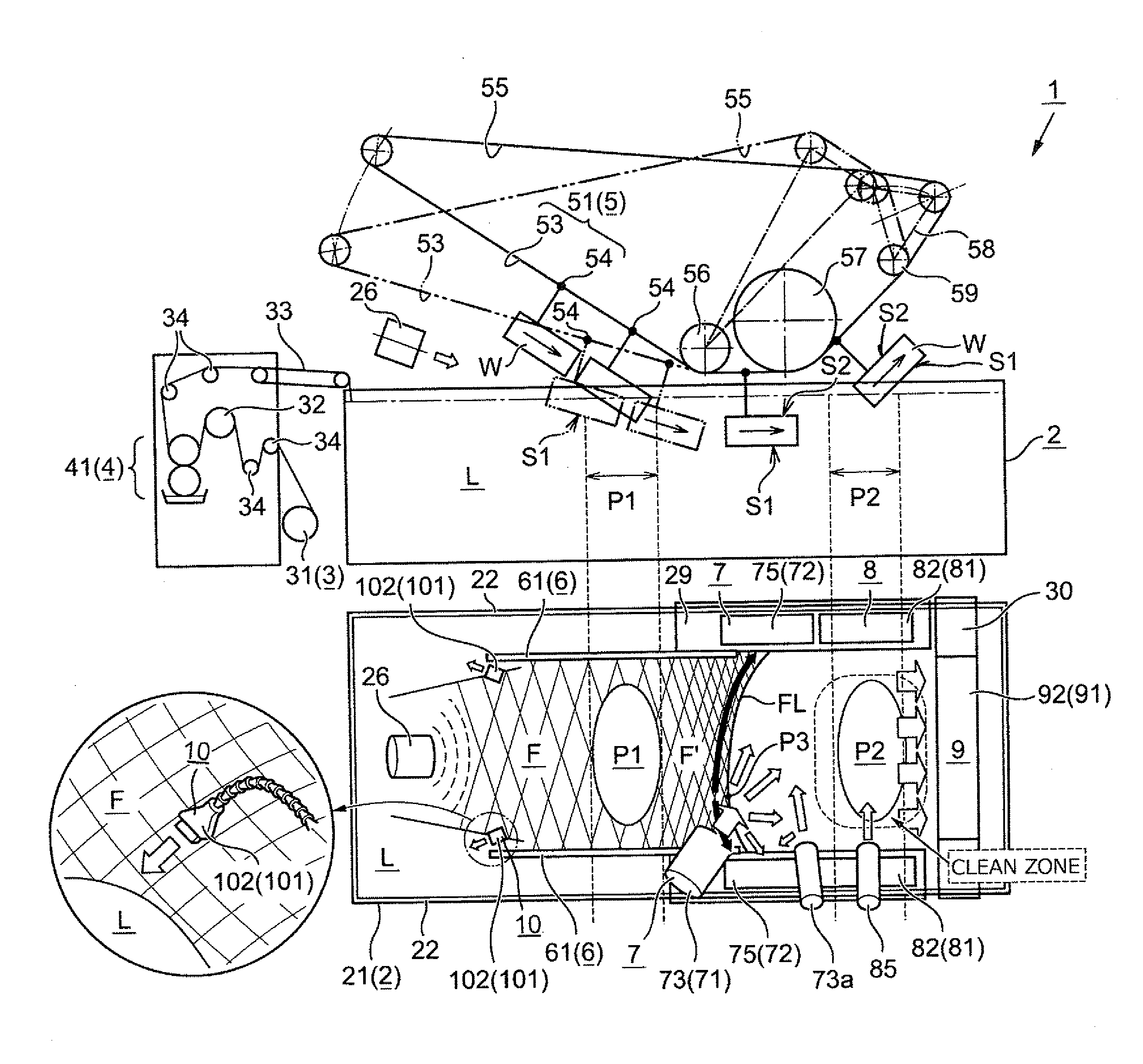
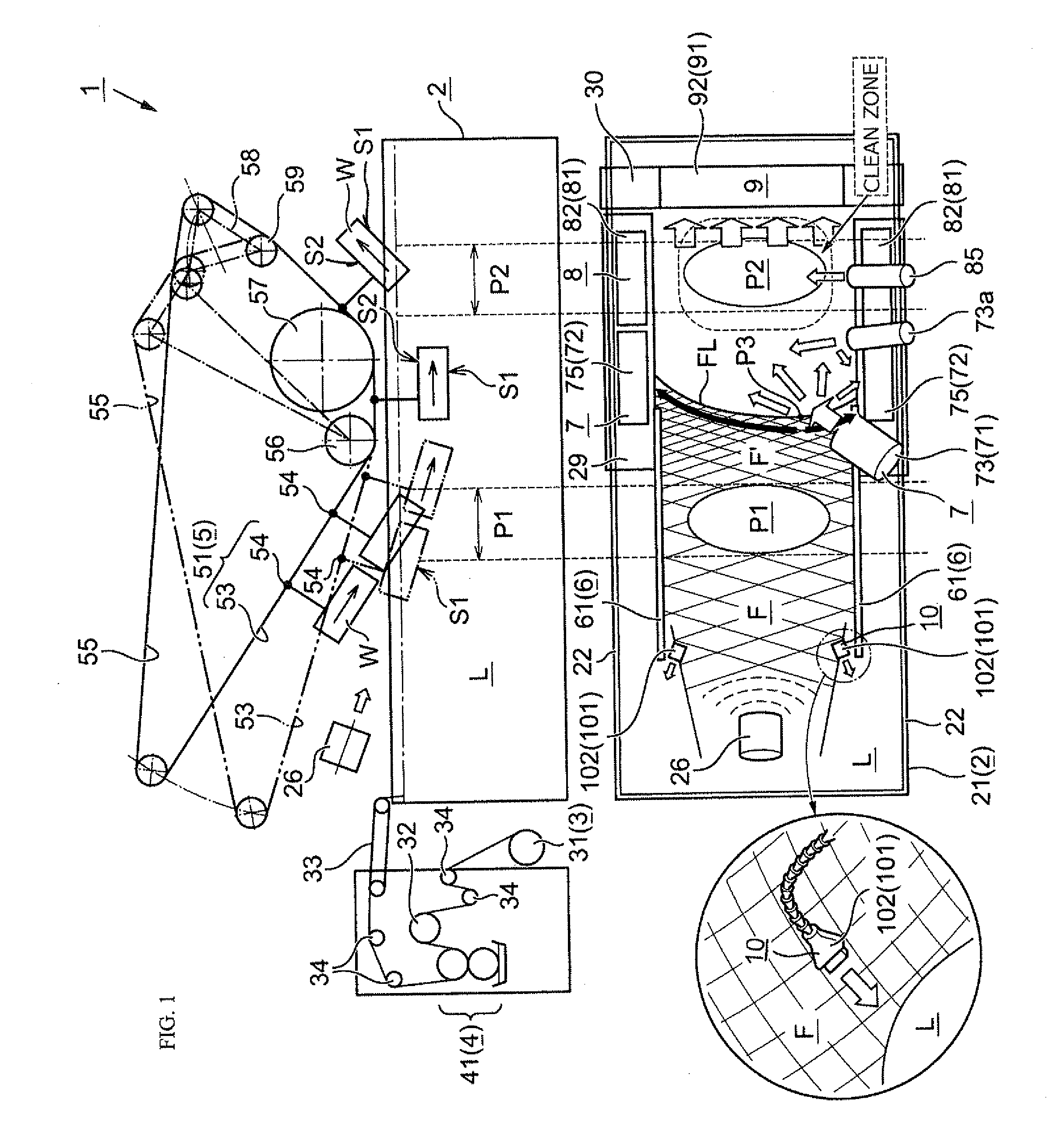
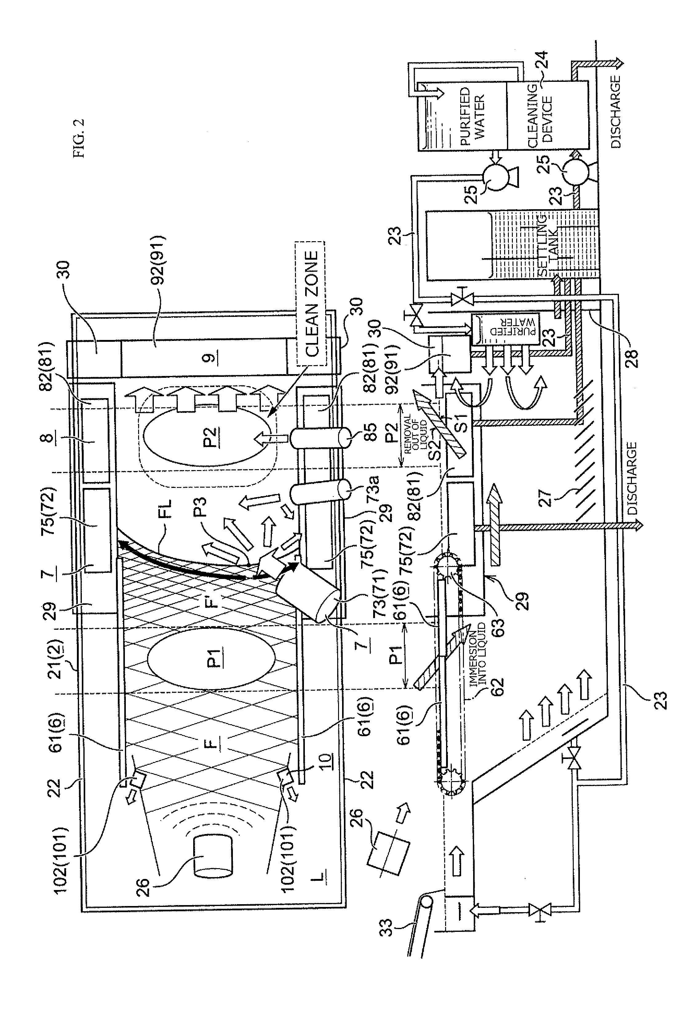
[0055]First, according to the invention described in claim 1, 14, 17, or 30, from when the object is immersed into the transfer liquid to when the object is removed from the transfer liquid, the liquid surface residual film is divided and is discharged (collected) from the transfer tank (collected). Therefore, after the transfer, the liquid surface residual film can be collected quickly and reliably. Accordingly, the liquid surface residual film does not reach the liquid-leaving area, and the liquid surface residual film can be prevented from being attached to the design surface of the objects which ascend successively from the transfer liquid.
[0056]In the present invention, the transferred liquid surface residual film is divided and collected, and therefore, the liquid surface residual film can be collected without deforming the transfer film before the transfer such as the transfer position. More specifically, for example, when the liquid surface residual film is tried to be collected without dividing it, the entire film including the film that has not yet been transferred may be pulled during the collecting process, and in such case, e.g., the film that has not yet been transferred is considered to be deformed.
[0057]According to the invention described in claim 2, 14, 18, or 30, the liquid surface residual film is divided by blowing air (air blow), and the air blowing device itself serving as the dividing means does not directly come into contact with the transfer film, and therefore, this can reduce, e.g., deformation that is exerted on the transfer film at the transfer position. More specifically, for example, when a rod and the like fixed in a hanging manner from the upper side of the transfer tank is brought into direct contact with the liquid surface residual film to divide the transfer film, certain force (deformation) is usually caused in the transfer film at the transfer position, back from the dividing start point. In contrast, in the present invention, the transfer film is divided by non-contact air blow, and therefore, the chance of giving adverse effects on the transfer film at the transfer position is extremely low. It is to be understood that the non-contact means that split pieces of the divided transfer films and the like would not attach to the dividing means (rod), and therefore, it is not necessary to replace and clean the dividing means, and the maintenance of the entire apparatus is easy.
[0058]According to the invention described in claim 3, 14, 19, or 30, the liquid surface residual films are collected by the overflow tanks, and the overflow tank is provided with blocking means for blocking the collecting of the liquid. Therefore, even in the same overflow tank, the liquid surface residual film can be collected at two stages before and after the blocking means, and the blocking means can also control the guiding flow rate of the collecting process. Therefore, the liquid surface residual film can be reliably collected without pulling the entire liquid surface residual film (without giving adverse effects on the transfer film at the transfer position).
[0059]According to the invention described in claim 4, 14, 20, or 30, the film holding mechanism is provided such that the end termination portion of the action of holding the film somewhat overlaps with the overflow tank. Therefore, the divided liquid surface residual films are reliably held by the film holding mechanism until the divided liquid surface residual films reach the overflow tanks, and it is possible to substantially solve the adverse effects of pulling the transfer film at the transfer position.

Problems solved by technology

However, in this kind of conventional liquid pressure transfer, first, solvent-based clear coating is used for the top coating, and there is a problem in that the environmental impact is high, and moreover, since, e.g., there is a defect during the top coating and it takes a relatively long time and energy in the coating and drying, the overall cost of the liquid pressure transfer increases.
However, in this kind of collecting method, the liquid surface residual films pass through the liquid-leaving area.
Moreover, these require extensive structure, and are batch processing method in which films and residues are collected on every transfer, and therefore, it takes a long time and the efficiency is low, which cannot be necessarily said a preferable method.

Method used


Image

  • Method for collecting liquid surface residual film, method for transferring liquid pressure using same, collection device therefor, and liquid pressure transfer device using same
  • Method for collecting liquid surface residual film, method for transferring liquid pressure using same, collection device therefor, and liquid pressure transfer device using same
  • Method for collecting liquid surface residual film, method for transferring liquid pressure using same, collection device therefor, and liquid pressure transfer device using same

Examples


embodiments

[0093]First, the transfer film F preferably used in the present invention will be explained. In the present invention, during liquid pressure transfer, only a transfer pattern is not simply transferred onto an object W, and it is preferable to transfer a transfer pattern also having a surface protection function (in this specification, such transfer pattern will be referred to as “transfer pattern also having surface protection function”). This is because a top coating, which was applied after the transfer in the past, is not needed. That is, in the liquid pressure transfer that also gives the surface protection function, the transfer pattern formed by the liquid pressure transfer is cured by emitting active energy rays such as ultraviolet rays and an electron beam to the object W to which the transfer pattern has been transferred, so that the surface can be protected. Nonetheless, it is also possible to further apply a top coating after the transfer pattern also having the surface ...


PUM


Abstract

A method for collecting a liquid surface residual film floating on the surface of the liquid after transfer, and a transfer tank that includes a film holding mechanism, provided at inner sides of both right and left side walls, for holding both sides of the transfer film and conveying the transfer film to an immersion area. When a film that is no longer needed after the transfer is collected, dividing means divides the liquid surface residual film so as to split the liquid surface residual film in a longitudinal direction of the transfer tank before the object is removed from the transfer liquid, and the divided films are moved closer to the both side walls of the transfer tank. At the side wall portions, the film holding mechanism is canceled, and from this canceled portion, the divided liquid surface residual films are discharged out of the tank.

Description

TECHNICAL FIELD[0001]The present invention relates to a liquid pressure transfer, in which a transfer film made by applying an appropriate transfer pattern (surface ink layer) with a transfer ink in advance is supported in a floating manner on a surface of a liquid, and while an object is pressed on the transfer film, the object is immersed into the transfer liquid, whereby the transfer pattern on the film is transferred onto the object using a liquid pressure thereof. More particularly, the present invention relates to a novel collecting method and a method for transferring liquid pressure thereof, wherein after the object is immersed into the transfer liquid, unnecessary residual films not used for the transfer and floating on the surface of the liquid are collected reliably and quickly, and the residual films do not reach the liquid-leaving area.BACKGROUND ART[0002]A liquid pressure transfer is known, in which a transfer film made by applying an appropriate water-insoluble transf...

Claims


Application Information

Patent Timeline
Patent Type & Authority Applications(United States)
IPC IPC(8): B08B5/00F17C13/00F17D1/00
CPCB44C1/175B41F16/006B44C1/1758Y10T137/0318Y10T137/85978B41F16/00
Inventor YOSHII, YOUICHIROSUZUKI, EIJIUSHIWATA, SAKAE
Owner TAICA
Why Eureka
Try Eureka